Dear all,
I'm new to the field, and appreciate any help...thanks in advance!
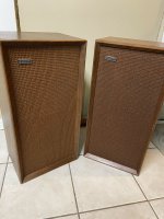
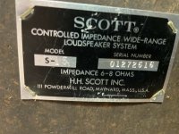
I inherited old Scott S-15 speakers (29 L). Some of the drivers were dead. I was recommended to change them (I changed all 6 of them) for the following ones:
I've also recaped the filters (with equivalent capacitors).
Now they sound pretty bad, and after running a quick test (using this), I am assuming the filters are not doing their job properly at all.
I've started to look into filter designing, but I must admit that I'm having a hard time figuring things out. I would very much appreciate any advice on the circuit I should build.
All the best,
Eli
I'm new to the field, and appreciate any help...thanks in advance!
I inherited old Scott S-15 speakers (29 L). Some of the drivers were dead. I was recommended to change them (I changed all 6 of them) for the following ones:
I've also recaped the filters (with equivalent capacitors).
Now they sound pretty bad, and after running a quick test (using this), I am assuming the filters are not doing their job properly at all.
I've started to look into filter designing, but I must admit that I'm having a hard time figuring things out. I would very much appreciate any advice on the circuit I should build.
All the best,
Eli
Welcome to the forum, Eli!
So, you have done a frequency sweep - what did that reveal?
In what way do they sound "pretty bad" on music?
Do you have a schematic for the current crossover?
So, you have done a frequency sweep - what did that reveal?
In what way do they sound "pretty bad" on music?
Do you have a schematic for the current crossover?
If you used the old crossover board with the new drivers (even with new capacitors), then it will not give the desired results.
What you need is for someone to design a three-way crossover that will suit the new drivers.
What you need is for someone to design a three-way crossover that will suit the new drivers.
Thanks for your answer Galu.
How I would describe the frequency sweep: the woofer covered 20-2800 Hz, then the tweeter took over (nothing seemed to came out of the midrange!). Here is how the filter looks now. It has a switch with 3 possible positions, which I'd like to get rid of (I would be very happy with a simple filter):

How I would describe the frequency sweep: the woofer covered 20-2800 Hz, then the tweeter took over (nothing seemed to came out of the midrange!). Here is how the filter looks now. It has a switch with 3 possible positions, which I'd like to get rid of (I would be very happy with a simple filter):
I'll try to drum up interest in your project by picking out some information on your replacement drivers:
1. A 240 mm, 8 ohm, paper cone bass driver from Audax.
2. A 124 mm, 4 ohm, open back, coated cone mid driver from Monacor.
3. A 90 mm, 8 ohm, paper cone tweeter from Monacor.
The enclosure is sealed and not ported - photos attached.
P.S. I've just seen your new post and will have a closer look at it.
Attachments


It's all a bit of a tangle in there!
It may take a younger, more agile mind than mine to turn your photo into a circuit diagram! 🙂
The obvious reason for the midrange not working is that you have made a wiring error when installing the new capacitors.
You will have taken a photo of the board before you worked on it, or so I would hope. 🤔

We couldn't simply guess what to do such as what filter to make, under the current circumstances that will compare to the current design.
So, it would be useful to know how the new drivers compare to the old, and how to adjust the current circuit. This means knowing what the current circuit is and what changes you've already made, as well as knowing about all the drivers involved. Also working out why the midrange stopped working.
Is any of this possible? We need to know where to start. Also, you mention a simple filter like you're saying you want to start from scratch?
Last edited:
If not possible, and you would like to get the speaker up and running in order to check that your replacement mid is working as intended, read on!
1. Unsolder all three drivers' wires from the board and remove the board from the amp input.
1. Run the woofer wires direct from the amp input.
2. Run the midrange wires from the input with 22 uF (or better, 32 uF) worth of capacitance in series with the positive wire.
3. Run the tweeter wires from the amp input with the 4.7 uF capacitor in series with the positive wire.
I choose the above values because you can take the 4.7 uF capacitor straight off your board, and can create the 22 uF capacitor by wiring the 10 uF and 12 uF capacitors from your board in parallel (side by side). I can't see the value written on the left hand capacitor, but if it is 10 uF then include it in parallel to get 32 uF and a lower frequency of filtration.
The result will be far from optimal, but it will get you going until you have a custom designed crossover schematic in your hands.
It's called experimentation, and you may learn something in the process.
P.S. Speaker designer AllenB is undoubtably now holding his head in his hands! 😱
Last edited:
I did take a picture of the filter before messing up with it, please find it below.
Good, you can carefully double-check your wiring.
The original crossover may not be optimal for your replacement drivers, but it should at least allow the midrange driver to work.
I did double-check, and I can't find anything...but I agree with you Galu, I must have made a mistake.
In the meantime, I followed your advice and made the 'simple filter' (see photo). All drivers work, and a frequency sweep does yield acceptable results (I mean that the two crossover frequencies are in the ballpark of what one expects with a 3-way system).
Now should I be happy with this? I guess inductors are usually in filters for a good reason .
.

In the meantime, I followed your advice and made the 'simple filter' (see photo). All drivers work, and a frequency sweep does yield acceptable results (I mean that the two crossover frequencies are in the ballpark of what one expects with a 3-way system).
Now should I be happy with this? I guess inductors are usually in filters for a good reason
.Well done!
With this simple crossover, the frequency ranges which the individual drivers reproduce will overlap somewhat. The addition of inductors (and other capacitors) would reduce the degree of overlap between the drivers which, technically, should result in a smoother reproduction.
However, many vintage speakers operated with simple crossovers such as this. The bottom line is, if it sounds good, then it IS good!
If you want to dive in deeper, you will need a multimeter with an inductance scale with which to measure the inductances (in mH) of the inductors in your original crossover. This would let us see what component values we have to work with.
P.S. If either the midrange or tweeter sound a little too loud, place a resistor between the positive amp terminal and the filter capacitor. I see values of 1.7 ohm and 4 ohm (amongst others) on the board with which you can experiment. Have fun! 🙂
Last edited:
One other thought, I hope the replacement open-back midrange driver is in its own little sealed enclosure inside the main enclosure - just like the original one was, as shown in your link: https://tryphonblog.com/h-h-scott-s-15/
This is necessary to prevent the back pressure from the woofer exerting unwanted forces on the cone of the midrange.
This is necessary to prevent the back pressure from the woofer exerting unwanted forces on the cone of the midrange.
Again many thanks for your advice Galu.
Sadly no, the replacement midrange is just there 'freely' (like the other drivers).
Sadly no, the replacement midrange is just there 'freely' (like the other drivers).
Just thinking aloud, already very good suggestions above.
* speakers chosen are "almost" fine, except midrange, you need an 8 ohm one, not 4 ohm, replace it.
* the ultra-simple crossover chosen is fine for basic testing, but now get a generic 3 way one.
No doubt distinguished Forum members will suggest adequate crossover frequencies.
Using a straight woofer + a simple cap coupled tweeter "works" because you have a "built.-in" inductor in series with woofer, its own voice coil inductance (+ mechanical "inductance") but when you add a midrange, the building starts to crumble.
Even worse because the midrange chosen has too low impedance, your amp won´t like it at all.
* Plan B: make a list of what elements you already have, a crossover savvy guy may design/redesign/reverse_engineer the original one so you can rebuild it the proper way.
Not suggesting you try to rewire or correct the one you have, because by now we lost track of the modifications/errors, it´s much saner to strip all wiring and start from zero.
In any case, no PCB needed, just glue parts in place and wire them as needed.
The original parts DID work in the past.
Just praying you did not misread some original capacitor value and bought a wrong one 🙁 but we have the original photo as a guide.
Meaning you don´t really have to spend extra money, just some time and effort.
* as mentioned above, it is essential you isolate midrange cone from the murderous high pressure created by woofer.
5 pieces of wood will do, some cabinets used a piece of thick cardboard tube (with end sealed of course) or you might get a 10/15 cm long piece of 10/12 cm diameter PVC pipe, for which flat end caps are available, you can fix it to cabinet by applying a generous bead of silicone sealant all around.
I am surprised the original cabinet did not isolate midrange, or was it a sealed back unit?
If you still have it, post a picture from sideways or back.
- Home
- Design & Build
- Construction Tips
- Revamping Scott S-15 speakers