What bipolar transistors would you recommend for robust totem pole outputs at approximately 22khz or higher? Should I use heatsinking? Do I need TO247 sized bipolars to drive these massive MOSFETS?
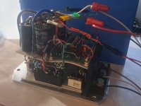
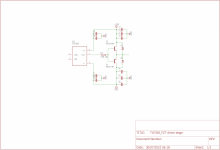
I'm building a TL494 based SEPEX motor controller that is switching huge 11X (eleven paralled) IRFP90N20D MOSFETS, with 10 ohm gate resistors on each MOSFET, and I'm using 6A darlington Sanken TO-220 drivers for them, and also smaller 5A TO-126 audio transistors driving one pair of IRFP90N20D Pin a typical NPN/PNP totem-pole arrangement. They are getting REALLY HOT. I'm rebuilding my circuit over again with single side prototype board, because I discovered the double-sided prototype board has issues with capacitance and shorting, even though the circuit works, which is adding to the heating. I never had issues with plain prototype board, but the green double board looks nice, and was a nightmare to work with!!!
Before I rebuild this circuit on to new prototype board, what recommendations would you make?
Attachments
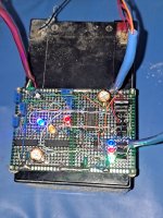
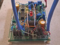
Found my totem pole part numbers B1626 and D2495 (6A) For TO220 and B1151 and D1691 for TO126 (5A) which I thought was overkill for totem poles, just for FYI, I'm not a novice, but I'm not prototyping with these green boards anymore, as the TO220 are too hot to touch, and I still got heat from the TO126 devices even with MOSFET disconnected, but the control board pulled only 300mA from 12V source, so I'm baffled. Rebuild is coming, I didn't post schematic because it's hand drawn and takes 4 pages.
TL494 isnt the quickest output driver on the block, add to that the fact your driving quite a bit of capacitance your fall-times are too long causing your mosfets to be in linear conduction region for too long.
The culprit is the darlington you are using, its creating a very slow turn-off squarewave cause of its lousy fall time. you would do much better by taking a couple of fast BJT's and not darlingtons. but there is an integrated solution. IXDN602PI is a very fast mosfet driver with 6A current capability.
The culprit is the darlington you are using, its creating a very slow turn-off squarewave cause of its lousy fall time. you would do much better by taking a couple of fast BJT's and not darlingtons. but there is an integrated solution. IXDN602PI is a very fast mosfet driver with 6A current capability.

I am considering IXDN602PI IC chip driver, but saw only a 2A rating on it. Can it be paralled?
The TL494 HAS to stay, the throttle control works perfectly! I have used TL494 flawlessly at 80-100khz in other projects before. The motor control is SLOW by comparison.
Tl494 has the dual input amps and sync of 2 chips which gives me exactly the features I need for gain and comparator turn on when I press throttle, to exactly calibrate throttle range, and to control armature AND field. I am only going for approx 20khz, may even lower it to 10khz possibly.
What about a pair or 2 of MJE15030/31 on heatsinks to drive the MOSFETS? My MOSFETS run cool, it's the totem drivers getting really hot. I'm considering 33ohm ohm out of TL494 to feed BJT Totems, and 680 ohm X2 pull down (340ohm) and hopefully that has enough drive power for the MOSFET Gates.
Yes you can parallel two channels on the 602 mosfet driver.
I like the FZT1049 and FZT1149 for these kind of jobs. they have remarkably low VCEsat so they dont run that hot if you drive them hard.
What i would do is the following parallel two channels of the mosfet driver, and use those zetex transistors, behind the 2X2A mosfet driver. With 22R 1W base resistors.
The problem you are dealing with, is that you are trying to keep the driver transistors in saturation whilst they have to deliver 10-14A! for a very short time. For that you need high gain devices that switch fast. and those zetex parts fit the bill. The mosfet driver is nice because its schmitt trigger input means it takes the slow pulse out of the 494 and it translates it into a fast squarewave.
Wow, didn't realize peak switching was 10-14A!!! If the MJE15030/31 can do it, that's cool.
I did discover short in the board after going over all solder joints as well, and my TO126 section for switching only one MOSFET gets hot without MOSFET even connected, so I must also be getting cross conduction, as I never had problem with even TO92 devices or To220 MJE15034/35 in past, so I am rebuilding entire circuit, I'm just wondering if I can save time without the gate drivers? If not, I may have to order more parts from different places...
I did discover short in the board after going over all solder joints as well, and my TO126 section for switching only one MOSFET gets hot without MOSFET even connected, so I must also be getting cross conduction, as I never had problem with even TO92 devices or To220 MJE15034/35 in past, so I am rebuilding entire circuit, I'm just wondering if I can save time without the gate drivers? If not, I may have to order more parts from different places...
That wont work well. upslope will be relatively quick, but turn-off will be slow, and given that most of your power dissipation will happen on the downslope your circuit will entail higher mosfet power dissipation.
This is because when switching inductive loads, your current will be higher at switch-off than during switch-on.
What i would do is the following: get a DC/DC module that spits out +-12V at a couple of watts, and use a TLP358 with FZT1049/1149 buffer.
At 20Khz and 10nF per fet, 10 fets for the sake of math, you have to charge 100nF 20K per second to 12V and discharge it into -12V 20K times per second.
https://www.mouser.de/pdfdocs/Power_Integrations_AN1001.pdf
From that formula one can gather that power requirements will be sub 1W from the DC/DC converter, owning to your relatively slow switching frequency. but i would look for a 3-5W DC/DC
Attachments
Try using CFP pairs for the driver followers. High speed small signal inputs, driving high speed high CURRENT devices like D44/45. Use sub-100 ohm speed ups on the output Vbe’s. Reduce the gate resistor to like 4.7 ohms, and put a large-ish schottky diode pointed backwards in parallel with that. That will give you 3 AMPS of positive drive capability, and 10 or more during turn off.
I really like this idea, CFP is great for audio amplifiers!Try using CFP pairs for the driver followers.
Should I still heatsink, or just let some large transistors run hot naked?
TO-220 is nice for PCB space, but I'm considering pure ridiculousness and going for some TO-247 only if necessary. (Original controller only had 91ohm gate resistors on 8X IRFB4310 with IR2110 driving TO-92 totem pair)
Trying to finish this electric car quickly! I almost had it on the road! (Thanks for all comments and help)
Attachments
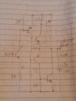
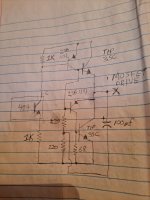
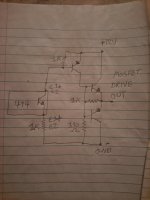
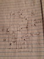
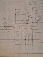
Correction to allow better bootstrap, and still saturate at narrow pulse width without the 0.7V diode loss on pull-down. Changed resistor values to lessen resistor heat dissipation, since there will now be some drive below the rail.
I am hoping this will achieve approximately 1V saturation or less, since TL494 Emitter output driving a standard NPN/PNP totem loses over 2V, which is not much when driving with 12V. Comments welcome!!!
I am hoping this will achieve approximately 1V saturation or less, since TL494 Emitter output driving a standard NPN/PNP totem loses over 2V, which is not much when driving with 12V. Comments welcome!!!
Attachments
Last edited:
I like the TLP358 and FZT buffer solution as well. Mentioning a negative rail also gave me the bootstrap idea.
I'm going to use the discrete NPN without a heatsink, since the little FZT don't need a HS. The large TO-247 transistors will have enough surface area, and still take up very little PCB with no HS. At their high rating, even IF they get hot, they will be ok.
Before, I was losing nearly 3V (measured) with the TL494 emitter output and darlingtons, giving me barely over 10V with 12.7V power supply. With higher drive voltage, and better saturation, I expect much cooler temperatures.
Since TO-220 supports 2W free air, the TO-247 will be fine without heatsink. I will let you know if my MOSFETS run even cooler as well unloaded, as I'M sure once the car is on the ground, the increased load will heat everything up, so the cooler, the better....
I wouldn’t be using the slow TIP35/6. I suggested the D44/5 pair because of the 50 MHz fT, and the fact that the package is still relatively low inductance. TO247 is MUCH higher. And you do need at least a couple ohms in the gate circuit. The series L can and will resonate with the mosfet input capacitance and if you don't damp the ringing, dead mosfet. That **** won’t show up in a simulation either - unless you add package and PCB layout inductances. You do want a very tight layout of a driver like that or you defeat the entire purpose. The two collectors can be directly bolted together.
I normally wire a TL494’s output transistor as a pull-DOWN, with the resistor in the collector circuit. That forces turn off time to be the faster of the two (In the mosfet). And you can have asymmetric resistance using the steering diode at the output, but that adds inductance.
I normally wire a TL494’s output transistor as a pull-DOWN, with the resistor in the collector circuit. That forces turn off time to be the faster of the two (In the mosfet). And you can have asymmetric resistance using the steering diode at the output, but that adds inductance.
You are right, I missed the 3mhz FT in the datasheet of TIP35. Also the 2SB1151 are slower than I thought, which explains their heating also....I wouldn’t be using the slow TIP35/6. .....And you do need at least a couple ohms in the gate circuit. The series L can and will resonate.....
I'm also assuming you mean to add a single gate resistor/diode to feed the multiple 10 ohm MOSFET gate resistors? Maybe 1 or 2.2ohm?
As far as using TL 494 to pull-down, the problem would be the inverted PWM signal, that's why it IS a pull-down, driving the inverting PNP to pull-up. I did that to drive closer to the rail. My PNP drive, with resistor in the emitter was copied from the datasheet example.
I still like the CFP output option, although I'm concerned with cross-conduction, but maybe that only applies to audio....interesting....
Just went through many datasheets of switching transistors, and even low ft ones will be used in switching circuits of well over 20khz, 2SC5583 for example, only 3mhz, but really short fall time. I think I just need stronger drive, more than fast transistors, and it should be fine. I also can lower switching frequency, I don't have to be at 20khz for the motor, I can switch at 10khz, a little motor whine, if any won't bother me. Input is appreciated, ill build a test circuit, and check results before I finish this controller.
Update, did some rework of original circuit before building my new test board. Definitely want to redesign drive, as TL494 outputs 10.2V, and after totem, getting only 9.6V for the MOSFETS, so I believe more drive would help, unless I just feed circuit 15V instead of 12V. Literally 2.5V loss at chip, no wonder they were NOT the best drive for car amps!!!!
Heat in my TO126 parts was just absorbed heat, found the short in board, also removed and relocated some wires, still have heat in darlingtons, ESPECIALLY the PNP, but the top darlington is surprisingly saturating within 1V, but the down drive (680ohm) could be better, as I do have some heat in MOSFETS unloaded, so I may add another 680ohm to the darlington to increase drive, but I am using this board for just testing, as I am rebuilding. The temp is actually in spec around 100C, but IMO still too hot.
Heat in my TO126 parts was just absorbed heat, found the short in board, also removed and relocated some wires, still have heat in darlingtons, ESPECIALLY the PNP, but the top darlington is surprisingly saturating within 1V, but the down drive (680ohm) could be better, as I do have some heat in MOSFETS unloaded, so I may add another 680ohm to the darlington to increase drive, but I am using this board for just testing, as I am rebuilding. The temp is actually in spec around 100C, but IMO still too hot.
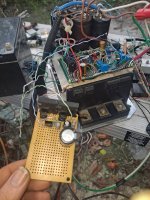
Built test board, and fed the original board TL494 PWM emitter output into it, (with original totem disabled)
Because of voltage gain, I got 0.59V Saturation, and ZERO heat from the NPN outputs, only one 1/2w 300ohm resistor gets hot. Mosfets getting over 12.3V drive!!!!
I know my choice of low gain TO264 2SC5583 switching transistors seems absolutely ridiculous, but it's an experimental test board, and now will allow me to design better totem pole with smaller parts, and will allow me to use the controller until I rebuild the new board! I can get switching NPN way easier than complimentary pairs all day!!! They are fast enough to drive a CRT flyback, so they should be fine. I bet I could use common MJE13007 switching transistors with PNP drivers and get similar results,
Attachments
- Home
- Amplifiers
- Power Supplies
- HOT Totem Pole transistors, alternatives?