Inspired by the short thread on Vendor's Bazaar:
https://www.diyaudio.com/community/threads/nad-3020-clone-pcb-kit.388467/#post-7080981
I started thinking about making a tribute amp based on the essence of the famous NAD 3020.
The NAD 3020 was my first amp and I loved it. It sounded good, also playing loud on my Cerwin Vegas and later on my DIY 3 way based on Peerless, ScanSpeak and Dynaudio.
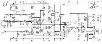
Looking at the original schematics, there are things I would like to simplify quite a bit.
1. The power supply needed is complex, with +-28V, 29,9V and -25,6V ....... would be much easier with just a single +- PSU
2. The power supply for the input stage is regulated, and in the later model 3020i this is also true for the main output PSU. Is this really necessary?? I would guess that the input stage has less PSRR then would be the case for a differential pair.
3. Changing the transistors and components to SMD as much as possible / feasible, and also changing to types readily available in 2022
But what is the essential in this legendary amp?
And would it at all make sense in todays drift towards Class D?
Is the good sound just a good old memory 😉 ?
I would think the essence is the input and VAS configuration, and this is what I would keep. It is not symmetrical, with no diff input and no current mirrors. This would imply higher even distortion, as these steps would reduce exactly even order.
I would go for relatively low power with say +-35V. This could easily be provided by a cheap regulated SMPS, and would be a big improvement over the original PSU of a stock 3023
I have been doing some LTSpice sims, of both the original and a modified version .... stay tuned
https://www.diyaudio.com/community/threads/nad-3020-clone-pcb-kit.388467/#post-7080981
I started thinking about making a tribute amp based on the essence of the famous NAD 3020.
The NAD 3020 was my first amp and I loved it. It sounded good, also playing loud on my Cerwin Vegas and later on my DIY 3 way based on Peerless, ScanSpeak and Dynaudio.
Looking at the original schematics, there are things I would like to simplify quite a bit.
1. The power supply needed is complex, with +-28V, 29,9V and -25,6V ....... would be much easier with just a single +- PSU
2. The power supply for the input stage is regulated, and in the later model 3020i this is also true for the main output PSU. Is this really necessary?? I would guess that the input stage has less PSRR then would be the case for a differential pair.
3. Changing the transistors and components to SMD as much as possible / feasible, and also changing to types readily available in 2022
But what is the essential in this legendary amp?
And would it at all make sense in todays drift towards Class D?
Is the good sound just a good old memory 😉 ?
I would think the essence is the input and VAS configuration, and this is what I would keep. It is not symmetrical, with no diff input and no current mirrors. This would imply higher even distortion, as these steps would reduce exactly even order.
I would go for relatively low power with say +-35V. This could easily be provided by a cheap regulated SMPS, and would be a big improvement over the original PSU of a stock 3023
I have been doing some LTSpice sims, of both the original and a modified version .... stay tuned
Attachments
there are things I would like to simplify quite a bit.
1. The power supply needed is complex, with +-28V, 29,9V and -25,6V ....... would be much easier with just a single +- PSU
2. The power supply for the input stage is regulated, and in the later model 3020i this is also true for the main output PSU. Is this really necessary?? I would guess that the input stage has less PSRR then would be the case for a differential pair.
3. Changing the transistors and components to SMD as much as possible / feasible, and also changing to types readily available in 2022
This sounds like a good recipe to turn the NAD into something substantially worse.
In the 80's i also had the 3020 and some of the bigger brothers like 3150. This ended with a number of clones, all of which sounded substantially better than the originals. Overbuilt power supplies, a separate transformer/rectifier for the front end, no soft clip, no resettable fuse at output, overall much better parts and proper termination.
Is it worth building an inferior copy?

Because you are generally constructing a new amp.
NAD´s doesn´t sound the way the do despite the components used but because of them.
SMD´s will give you worse heat dissipation.
It might work, and you will end up with something, that has absolutely no recemblance to the original NAD sound signature 😉
NAD´s doesn´t sound the way the do despite the components used but because of them.
SMD´s will give you worse heat dissipation.
It might work, and you will end up with something, that has absolutely no recemblance to the original NAD sound signature 😉
The 3020 has discrete components crammed into a weird case so it would be a challenge to replicate. I have an old C 320BEE which also has a lot of discrete with little modules soldered into the main board. It has relays to select inputs and tone controls and a defeat switch. It is a dull but practical classic design.
NAD tried to repeat the success of the 3020 with the 3045. The 3045 is a computer with class D hypex module that runs hot in 3020 case. It needs a cooling fan if standing horizontal. https://www.diyaudio.com/community/threads/nad-d-3045-overheating-allegedly.379438/#post-7069133
NAD tried to repeat the success of the 3020 with the 3045. The 3045 is a computer with class D hypex module that runs hot in 3020 case. It needs a cooling fan if standing horizontal. https://www.diyaudio.com/community/threads/nad-d-3045-overheating-allegedly.379438/#post-7069133
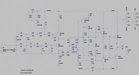
Well the thought is to re-use the input section and the VAS section, including boot strap (also used by e.g. AKSA), and only modify the output slightly .... so at least the topology would be the same.
As for SMD; for the input section I see no reason for not using SMD in 2022. There is close to no heat dissipation in the input, and you will be able to make a tighter layout with less noise.
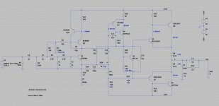
Transistors like 2SD1400, 2N6551 and 2N6554 are no longer available, and can be substituted with newer types. For the output I would suggest using 2SC5200N/2SA1943N in TO3P, for simplicity, cost and availability, and to be able to get a bit more power out.
At 10W@8ohm@1kHz, the original sim show H2: -88.0 db and H3: -89.5 db. The modified version shows H2: -90.4 db and H3: -95.6 db
The thought is to make physical small implementation on a 10x10 cm pcb, which could be udes with a similar size +-35V SMPS
Will it be the same? No of course not. It's meant to be a tribute, bringing up most of the topology to 2022 to celebrate the old NAD.
As for SMD; for the input section I see no reason for not using SMD in 2022. There is close to no heat dissipation in the input, and you will be able to make a tighter layout with less noise.
Transistors like 2SD1400, 2N6551 and 2N6554 are no longer available, and can be substituted with newer types. For the output I would suggest using 2SC5200N/2SA1943N in TO3P, for simplicity, cost and availability, and to be able to get a bit more power out.
At 10W@8ohm@1kHz, the original sim show H2: -88.0 db and H3: -89.5 db. The modified version shows H2: -90.4 db and H3: -95.6 db
The thought is to make physical small implementation on a 10x10 cm pcb, which could be udes with a similar size +-35V SMPS
Will it be the same? No of course not. It's meant to be a tribute, bringing up most of the topology to 2022 to celebrate the old NAD.
Attachments
Even if you upped the voltage to +/-35, which you can do if you don‘t insist on those old 2N3055’s, I would still keep the separate regulated front end. One of the reasons it’s NEEDED is to keep the DC offset under control when the supply sags. The base bias for the input transistor has to remain rock steady and that won’t happen if your supply is bouncing around. Hell, up it to +/-40 while you’re at it. Why? You could use the Antek AS-4428, which is off the shelf. Plenty of beef to “sound bigger than it is” AND has two auxiliary windings. Add 15-20 volts to each rail and regulate, keeping it a few volts above the main supply. There will be enough headroom that if the main supply sags 20% you still stay in regulation. When upping the voltage, you’ll have to decide whether to keep the same VAS load resistors (and have higher current in the VAS) or increase the value and keep the current the same. You can probably only gauge that by listening, unless you run into SMD dissipation issues which force you to a lower current. For outputs I’d use the 200 watt ON versions - either 21194 or 3281 at that voltage - depending on whether you buy into using higher fT outputs or not. If you wanted to keep the old TO-3 look you could go with anything 15003 and up, although 15024 or 2119x are the correct ones to use if emitter resistors will NOT be. Their internal construction has ballasting “resistors“ for the multiple internal paths on the dies. C5200 does NOT as far as I know, so I wouldn’t use those without emitter resistors. If you wanted a true Jap type for use without emitter resistors get Sanken LAPTs. Again, due to the internal ballasting which is HOW they get their high SOA. If you have any vintage types that have multiple emitter site structure they should be able to operate emitter-resistor-less if you keep the temp under control (don’t undersize the heat sink).
No worse than the Phase Linear Cult. Already a member there, so joining one more wont hurt. Remember that line in “Signs” about nerds making up secret societies? Just another real world example.
instead of taking a commercial budget amp and trying to make it into something its not (class D? SMD for what reason?) why not clone a truly legendary amp (PassLabs, Krell, Bryston, Threshold) and try get close to the sound of the original. Sure is will be difficult but both sound quality and street cred should increase exponentially
wg_ski ... think you are right about the biasing ... though I guess it would be feasible to just regulate the bias voltage .... but i again adds complexity. (a diff pair would be much easier ... but then it's not resembling a 3020)
I think that diving further in to make something which works really well, will require a lot of extras like output relay, DC servo etc. and then it's getting away from a simpler NAD3020.
I think I'm back to class d and smd 🙂
I think that diving further in to make something which works really well, will require a lot of extras like output relay, DC servo etc. and then it's getting away from a simpler NAD3020.
I think I'm back to class d and smd 🙂
Why repeat the past? How many times was trying to go back in the past successful?
A device that was affordable and good then may not be so appreciated today as it was back then.
A device that was affordable and good then may not be so appreciated today as it was back then.
Last edited:
jean-paul ... I think nostalgia is the word ...but it seems people in this forum is not much into nostalgia 🤣
Many people here are into nostalgia but then with original stuff from that time which is different. Nostalgia is for old people trying to go back in time and/or to relive the experience. Very often a disappointing experience.
Now getting the same emotion as then today with new stuff that is the real challenge!
Now getting the same emotion as then today with new stuff that is the real challenge!
Last edited:
Thanks i was looking for this.Well the thought is to re-use the input section and the VAS section, including boot strap (also used by e.g. AKSA), and only modify the output slightly .... so at least the topology would be the same.
As for SMD; for the input section I see no reason for not using SMD in 2022. There is close to no heat dissipation in the input, and you will be able to make a tighter layout with less noise.
Transistors like 2SD1400, 2N6551 and 2N6554 are no longer available, and can be substituted with newer types. For the output I would suggest using 2SC5200N/2SA1943N in TO3P, for simplicity, cost and availability, and to be able to get a bit more power out.
At 10W@8ohm@1kHz, the original sim show H2: -88.0 db and H3: -89.5 db. The modified version shows H2: -90.4 db and H3: -95.6 db
The thought is to make physical small implementation on a 10x10 cm pcb, which could be udes with a similar size +-35V SMPS
Will it be the same? No of course not. It's meant to be a tribute, bringing up most of the topology to 2022 to celebrate the old NAD
Using c5200 & 1943 for output is a good idea.
But does the modified schematic will sound like original amp. Or did you build it?
- Home
- Amplifiers
- Solid State
- NAD 3020 Tribute .... would it make sense?