The balance pot does affect the THD as well as the harmonic spectrum. Minimum 2H is not always at the point where the driver plate voltages are equal. I preferred the sound of a little extra 2H on some music. Some of my 6CB6's could not be balanced with the pot. The 6EW6's were better, the only ones that wouldn't balance were well used, but still sounded good.Pete's DCPP boards have balance pots for the 6CB6's (or whatever you're using), so the tubes should balance unless the specs are wildly different, which is entirely possible. So don't see why you couldn't incorporate this feature in your amp. Or did I miss that already.
jeff
Maybe it's just me, but I have never liked a bunch of GNFB on any amp I made.George mentioned he uses only about 6 to 8 dB NFB combined, and preferred shunt local feedback around the output tubes but didn't like the sound from the combination of shunt-local NFB plus gNFB.
You can't put a FW bridge on the bias tap since a FWB requires a floating secondary and one side of your bias winding is already grounded. This will short one diode in the bridge when its positive terminal is grounded making life very short and unhappy for the diode and possibly your transformer. I built two amps using Petes big red board. One is still floating around here somewhere, and I gave the other to my boss when I left Motorola. The test board seen in all of my experiments is on a nearby shelf, but it has not seen power since I moved here. Both completed amps used the "ten pounds of power" transformer mentioned in the thread. It had a dedicated bias winding that worked with a FWB. You are probably best off with a small, dedicated transformer.Reading Pete M's DCPP page a bit more, I see that he derived the -60VDC supply from a 50V-0-50V secondary on the Edcor power transformer he specified. I'm using a Dyna PA-060 power transformer, which has a 55V 'bias tap'. If I use a full-wave bridge on that bias tap, do you think it can deliver the -60VDC at 35mA I'll need for the tail supplies to the two 6CF6 LTPs? Do you think the PA-060 bias tap can stand up to that abuse, or do I need to add a separate, small transformer for that -60VDC supply?
Pentode LTP's seem to work best with high Gm tubes. 6AK5 Gm = 5000, 6CB6 Gm = 8000, 6EW6 Gm = 14000, 6GU5 Gm = 15000. The 6AK5 need not apply for this job. Too bad, I had about a thousand of them.What about 6AK5? That's another 7-pin pentode with the same pinout as 6CB6, 6EW6, etc.
Thank you George, that's a big batch of great info!
I think since I have two sleeves of 6CF6 already, I might as well use them. I'll look for some 6EW6 or 6GU5. Maybe a batch will pop up for cheap somewhere. Like you said earlier, it looks like 6EW6 will drop right into the circuit as designed for 6CF6, down to the value of screen grid dropping resistor.
Like you, I've never liked the sound of a lot of global NFB around an amp. For me, it always makes the sound kind of dull and flat (for lack of a better way to describe the sound). Then again, I actually like the sound of push-pull 2A3s or 300Bs... a lot. That's why I'm itching to try an amp with local shunt feedback around the output tubes, and I have this gutted Stereo 70 taking up space up on the shelf...
I didn't think through the FW bridge on bias tap idea. Yes, that would be dumb. Oh well. I have a 12.6-0-12.6 450mA transformer I could use with a voltage doubler to make just enough DC volts to light up a DN2540.
OK, if high gm is what is wanted for the pentode LTP, what about the used-to-be-cheap 6J9P (similar to 6688 or E180F)? Claimed gm is 15mA/V, and I have some.
I also have some 6J51P (6EJ7/EF184), which looks really good too.
Of course these are 9-pin mini...
I also have some 6J51P (6EJ7/EF184), which looks really good too.
Of course these are 9-pin mini...
Attachments
Last edited:
6EJ7's work good, as does the 6HB6, 6JC6 and 6JD6. The remote cutoff tubes like the 6EH7, 6KT6 and others with the same pinout work too as their distortion is mostly 2H which largely cancels in this circuit and doesn't sound bad. I have tried all of these in the same circuit with good results and only a bias tweak.OK, if high gm is what is wanted for the pentode LTP, what about the used-to-be-cheap 6J9P (similar to 6688 or E180F)? Claimed gm is 15mA/V, and I have some.
I also have some 6J51P (6EJ7/EF184), which looks really good too.
Of course these are 9-pin mini...
I have some 6688's but have not tried them due to the different pinout.
For what it's worth, as part of my Pandemic Anxiety Reduction (PAR) 2 years ago I designed a board very similar to this to fit a Dynaco chassis.
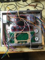
The amp shown below had a Hammond 290FX PT, 6GU5s and 38HE7s as finals.
Underneath there is a PS choke and a transformer for the 21 volt 38HE7 pentode filament (can be isolated and leave the damper diode dark).
I powered C- from the 50vac tap on the 290FX.
I had a slight hum in the amp especially in one channel that may have been due to the filament tranny mounted underneath. This amp has been taken apart and repurposed since.
The way I setup the C- is you can half wave or full wave rectify it either by inserting one diode or even a FW bridge rectifier part. I also have provisions for regulated screens for either just the small tubes on the board or, in the case of the amp in the picture, was also used for the screen volts for the sweep tubes. You probably could skip the heat sink if just powering screens for the small tubes.
BOM attached (very beta, like the board).
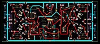
Also att is a diagram I was using for varistor protection on the output tubes that is also on the board. At the time I was using an "autobias" board but have since become a non-fan of these.
Today I'd remove the varistor stuff and put bias pots on the board for the finals. Also I'd rename the parts conventionally. I found it much easier when laying out the board to use mnemonics for the parts so I could associate the huge mess as I laid it out.
Those are Toroidy 4k cathode feedback OPTs.
I did this in DesignSpark (free).
The amp shown below had a Hammond 290FX PT, 6GU5s and 38HE7s as finals.
Underneath there is a PS choke and a transformer for the 21 volt 38HE7 pentode filament (can be isolated and leave the damper diode dark).
I powered C- from the 50vac tap on the 290FX.
I had a slight hum in the amp especially in one channel that may have been due to the filament tranny mounted underneath. This amp has been taken apart and repurposed since.
The way I setup the C- is you can half wave or full wave rectify it either by inserting one diode or even a FW bridge rectifier part. I also have provisions for regulated screens for either just the small tubes on the board or, in the case of the amp in the picture, was also used for the screen volts for the sweep tubes. You probably could skip the heat sink if just powering screens for the small tubes.
BOM attached (very beta, like the board).
Also att is a diagram I was using for varistor protection on the output tubes that is also on the board. At the time I was using an "autobias" board but have since become a non-fan of these.
Today I'd remove the varistor stuff and put bias pots on the board for the finals. Also I'd rename the parts conventionally. I found it much easier when laying out the board to use mnemonics for the parts so I could associate the huge mess as I laid it out.
Those are Toroidy 4k cathode feedback OPTs.
I did this in DesignSpark (free).
Attachments

Last edited:
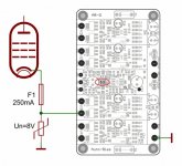
You should add a diode between the cathode current source (drain of DN2540) and ground. I assume that during power up the -64v supply will show up well before the 6CB6 tubes get a chance to warmup and provide current. That will cause the cathodes to be pulled close to your -64v supply while the grids remain at ground level. Not a healthy situation for the tubes. Adding the diode will limit the cathodes to -0.6 volts below the grids during startup. Then once the tubes get a chance to warm up the diode will drop out of the circuit as the cathode voltage reaches your indicated 2.72v. The diode will provide the current for the current source rather than the grids of the 6CB6 tubes during startup.For what it's worth, as part of my Pandemic Anxiety Reduction (PAR) 2 years ago I designed a board very similar to this to fit a Dynaco chassis.
The amp shown below had a Hammond 290FX PT, 6GU5s and 38HE7s as finals.
Underneath there is a PS choke and a transformer for the 21 volt 38HE7 pentode filament (can be isolated and leave the damper diode dark).
I powered C- from the 50vac tap on the 290FX.
I had a slight hum in the amp especially in one channel that may have been due to the filament tranny mounted underneath. This amp has been taken apart and repurposed since.
The way I setup the C- is you can half wave or full wave rectify it either by inserting one diode or even a FW bridge rectifier part. I also have provisions for regulated screens for either just the small tubes on the board or, in the case of the amp in the picture, was also used for the screen volts for the sweep tubes. You probably could skip the heat sink if just powering screens for the small tubes.
BOM attached (very beta, like the board).
Also att is a diagram I was using for varistor protection on the output tubes that is also on the board. At the time I was using an "autobias" board but have since become a non-fan of these.
Today I'd remove the varistor stuff and put bias pots on the board for the finals. Also I'd rename the parts conventionally. I found it much easier when laying out the board to use mnemonics for the parts so I could associate the huge mess as I laid it out.
Those are Toroidy 4k cathode feedback OPTs.
I did this in DesignSpark (free).
I would use an input bridging transformer to split phase and lose the long tail and have more gain and have symmetrical negative feedbacks from the secondary taps to the input tube cathodes. 6AU6 is reportedly a good audio pentode used in many Heathkits. Some examples from the vintage era.


Last edited:
Thanks for the idea.
Do both of those designs use input step-up transformers? That would be where a lot of the gain comes from in those designs, and I don't have any good transformers like that. I do have a pair of Edcor 600:10k transformers, but those aren't great.
I do have a pair of Jensen 10k:10k transformers that are reputed to be quite good. Perhaps there's a way to use those to split phase and use a pair of higher gm pentodes (like 6EJ7 or 6JC6A) as the push-pull driver stage.
That's exactly the bridging transformers I am talking about. Basically they are 1:1 ratio at high impedance or anything above 10KΩ so it would not load down the source, especially if you have a tube tuner or anything tube device without cathode follower. Jensen (or Cinemag) transformers are wide bandwidth and used in so many professional gears. Ampex and Altec/Peerless also made quality bridging transformers with octal sockets. I like to use input transformers whenever possible. The WE and Altec circuits are just examples and often with step-up transformers, 1:4 or 1:5 ratio (600Ω:10K or 600Ω:15K), which is unnecessary for line input and too low input impedance. If your circuit has gain to spare sometimes a step-DOWN transformer can be used to your advantage. And a step-down transformer will always have wider bandwidth than a step-up transformer. A transformer is nature's best phase splitter and you don't even need a center tap, just two matched resistors to junction to ground and it frees up the headache of a phase splitter circuit. (Personally, I only like split-load type with tube.) They are not cheap but it saves you the time and money to solder in a phase-splitter circuit. Also it allows easier implementing feedback symmetrically. WE gears were mostly bracketed with transformers so the secondaries are often floating, cannot do single ended NFB, so they applied that from the plate, which gave them their sonic characters. Having input transformer allows it to filter out subsonic garbage and digital source sounds better subjectively. There are many creative ways to use input transformers, especially in the pro recording field. And you have the benefit of a balanced input as a bonus!I do have a pair of Jensen 10k:10k transformers that are reputed to be quite good. Perhaps there's a way to use those to split phase and use a pair of higher gm pentodes (like 6EJ7 or 6JC6A) as the push-pull driver stage.
Last edited:
This does look like a good use for my pair of Jensen 10k:10k input transformers. Thanks for the idea!
I modeled the proposed circuit using a 10k:10k input transformer for phase splitting and a pair of 6EJ7 for the push-pull driver stage. The predicted THD at 1W into 4 ohms is 0.02%, which I'm sure is overly optimistic. The simulation shows perfect cancellation of even harmonics, but in real life the inevitably mismatched tubes are going to introduce even harmonics. The gain is not increased, but there's enough -- 1.2V peak to full power.
My sources all have low impedance outputs, so fortunately, impedance matching is not an issue. But the removal of subsonic grunge should mean I can get away with a bit more NFB without before into LF stability issues. I plan on using no global NFB to reduce the likelihood of HF instability. I'm going to try a combination of local parallel feedback loops -- one output tube plate-grid, the other from output tube plate to driver tube cathode.
The output transformers are going to be Dynaco A430 from a Dynaco Stereo 70 amplifier (approx 5k:VC, 40W).
I thought the issue was exceeding the maximum cathode-to-heater voltage, which is +/-100V average. What is the issue if the driver tubes have -64V at their cathodes for a second or two while the grids are at 0V?
I modeled the proposed circuit using a 10k:10k input transformer for phase splitting and a pair of 6EJ7 for the push-pull driver stage. The predicted THD at 1W into 4 ohms is 0.02%, which I'm sure is overly optimistic. The simulation shows perfect cancellation of even harmonics, but in real life the inevitably mismatched tubes are going to introduce even harmonics. The gain is not increased, but there's enough -- 1.2V peak to full power.
My sources all have low impedance outputs, so fortunately, impedance matching is not an issue. But the removal of subsonic grunge should mean I can get away with a bit more NFB without before into LF stability issues. I plan on using no global NFB to reduce the likelihood of HF instability. I'm going to try a combination of local parallel feedback loops -- one output tube plate-grid, the other from output tube plate to driver tube cathode.
The output transformers are going to be Dynaco A430 from a Dynaco Stereo 70 amplifier (approx 5k:VC, 40W).
You should add a diode between the cathode current source (drain of DN2540) and ground. I assume that during power up the -64v supply will show up well before the 6CB6 tubes get a chance to warmup and provide current. That will cause the cathodes to be pulled close to your -64v supply while the grids remain at ground level. Not a healthy situation for the tubes.
I thought the issue was exceeding the maximum cathode-to-heater voltage, which is +/-100V average. What is the issue if the driver tubes have -64V at their cathodes for a second or two while the grids are at 0V?
Last edited:
Pete Millett used a 10k:10k input transformer here:
http://www.pmillett.com/push-pull_kt88_class_a_amp_with_universal_driver_pcb.htm
http://www.pmillett.com/push-pull_kt88_class_a_amp_with_universal_driver_pcb.htm
Thanks. Pete used different input transformers than what I have. The ones he shows have center tapped secondaries.
I believe the Jensen transformer I have is JT-11P4-1
https://www.jensen-transformers.com/wp-content/uploads/2014/08/jt-11p4-11.pdf
I believe the Jensen transformer I have is JT-11P4-1
https://www.jensen-transformers.com/wp-content/uploads/2014/08/jt-11p4-11.pdf
This is what I'm thinking now... The extra output tube plate to driver tube cathode FB network only introduces about 3dB of NFB.
The feedback loop formed by R15, C3, R7 and R16, C4, R8 introduces something like 12dB NFB.

The feedback loop formed by R15, C3, R7 and R16, C4, R8 introduces something like 12dB NFB.
Looks like your Jensen has 1:1.41 step-up ratio and about 3dB of gain.I believe the Jensen transformer I have is JT-11P4-1
https://www.jensen-transformers.com/wp-content/uploads/2014/08/jt-11p4-11.pdf
You can probably eliminate the 2.2uf caps from 6L6 plates to input tube cathodes if you calculate the voltage and resistor values right for their bias. One example is Western Electric 109B amp, also a PP 6L6 amp, in R1 and R13.

Interesting.
So, I tried it out (in simulation).
I replaced the two 100k feedback resistors (6L6GC plate to 6CB6 cathode) with 330k ohms.
I removed the 2.2uF caps.
I reduced the 120R shared cathode bias resistor for the 6CB6s to 100R, to keep the driver stage bias the same.
Gain of the amplifier went up. That's because the amount of NFB introduced by the 330k feedback resistors is 2dB less than from the 100k resistors with 120R 6CB6 shared cathode bias resistor.
So, gain of the amplifier went up by 2dB or so.
The funny thing is, THD went down, not up.
I expected THD to go up with gain, as usual.
Huh?
This is what I have going now. It has 6EJ7s as the driver pentodes (much higher gm than 6CB6)...

It's quite similar to the RCA 50-Watt Amplifier with 7027A outputs in the later RCA Receiving Tube Manual, but without the 7199 voltage amp-cathodyne phase splitter stages, and with a lot more plate current through the driver stage pentodes (a la Pete Millett), and of course with a UL-wired output stage.
So, I tried it out (in simulation).
I replaced the two 100k feedback resistors (6L6GC plate to 6CB6 cathode) with 330k ohms.
I removed the 2.2uF caps.
I reduced the 120R shared cathode bias resistor for the 6CB6s to 100R, to keep the driver stage bias the same.
Gain of the amplifier went up. That's because the amount of NFB introduced by the 330k feedback resistors is 2dB less than from the 100k resistors with 120R 6CB6 shared cathode bias resistor.
So, gain of the amplifier went up by 2dB or so.
The funny thing is, THD went down, not up.
I expected THD to go up with gain, as usual.
Huh?
This is what I have going now. It has 6EJ7s as the driver pentodes (much higher gm than 6CB6)...
It's quite similar to the RCA 50-Watt Amplifier with 7027A outputs in the later RCA Receiving Tube Manual, but without the 7199 voltage amp-cathodyne phase splitter stages, and with a lot more plate current through the driver stage pentodes (a la Pete Millett), and of course with a UL-wired output stage.
Last edited:

If R16 is NFB, isn't R20 positive feedback?funny thing is, THD went down
I do agree it is funny.
To make it so it gets NFB (not PFB) from R20 and R21, would I need to cross-couple R20 (to U2 cathode) and R21 (to U1 cathode)?
I'm in the process of simplifying the design, instead of complicating it. I'm looking at making it 'E-Linear' like the design by Bandersnatch, from a while ago...
https://www.diyaudio.com/community/...-push-pull-amp-need-help.131940/#post-1641087
http://www.pmillett.com/elinear.htm
http://www.pmillett.com/file_downloads/KT88_SCH.PDF
Last edited:
Both feedback paths look like negative feedback to me: output plate to input cathode (most common type) and output plate to output grid (Schade style). Am I missing something?
- Home
- Amplifiers
- Tubes / Valves
- Parallel-NFB Push-Pull 6L6 Amplifier Idea - Please criticize it!