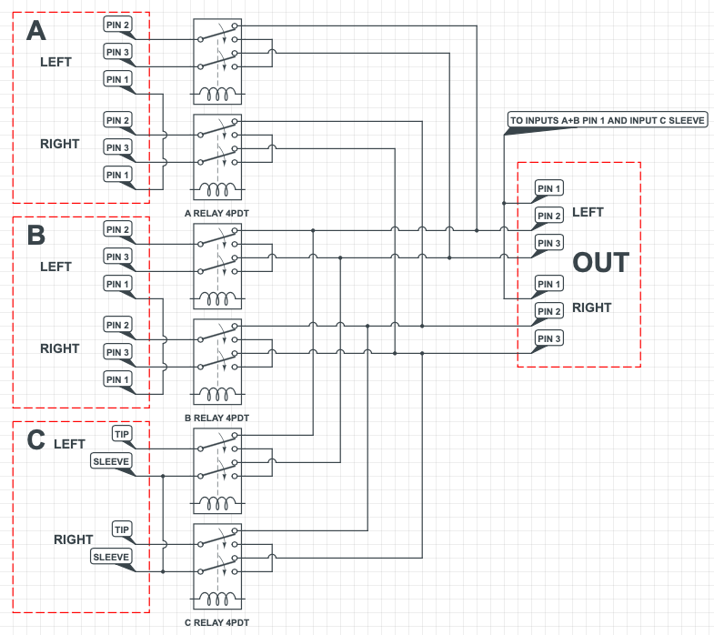
In the schematic all relays are shown on. In real world only one relay at the time is going to be active. Im not sure how to ground this thing so I started with ALL pin 1 tied together, both A/B, left/right and in/out. They are also connected to input C sleeve. NOTE its shown with 6 DPDT relays but I will use 3 4PDT relays.
1. Is the grounding correct?
2. Do I also connect pin1 and sleeve to the enclosure and DC negative?
3. Can I kill unselected inputs with short pin 2+3 and tip+sleeve?
XLR Input A is Apogee Duet soundcard
XLR Input B is Stereo DI
RCA Input C is Sonos Port Media Player
Output is going to a pair of Genelec 8240A monitors.
Last edited:
You are shorting out the inputs when they are not selected, which could be bad news for the source equipment.
If you want to have ultra-low crosstalk between sources they should each be buffered before the switching so that the active input is very low impedance and won't pickup capacitive crosstalk.
If you want to have ultra-low crosstalk between sources they should each be buffered before the switching so that the active input is very low impedance and won't pickup capacitive crosstalk.
The op-amp outputs are usually low impedance. Try first without buffering.
As what grounding concerns, Rane tells us pin 1 attaches to the enclosure and not to the circuit ground. (Pin 1 problem / dilema) assuming off course a metal case.
Non balanced connections usually short pin1 & 3 input at the input side.
I would use a TRS jack and maintain the balance and then a use a mono jack or RCA-jack adapter for non balanced gear, which will short Ground & Sleeve, So You can use balanced and un-balanced gear with the jacks.
Agreed.You are shorting out the inputs when they are not selected, which could be bad news for the source equipment.
If you want to have ultra-low crosstalk between sources they should each be buffered before the switching so that the active input is very low impedance and won't pickup capacitive crosstalk.
Pin 1 routing in this device isn't so critical since it does not do any signal processing per se, so basically there is only chassis ground to begin with.
The preferred way according to AES48-2005 (and in terms of RF) would be connecting pin 1 to chassis (enclosure) right at the jack. If that seems too tedious, I guess you could combine a few. Whatever you do, keep inductance down.
The control electronics may be connected to chassis ground but do not strictly have to.
What sort of power supply is this going to have - IEC Class I (mains earthed) or Class II (floating)?
Unbalanced input C still irks me. Your box is likely to be earthed by at least one of the devices attached. I am assuming the streamer has a little wall wart supply with no PE connection? What about your Ethernet cabling then? We like our shielded stuff around here, I know other areas of the world are more into UTP.
The crux is this:
If the streamer is floating in thin air, you'd want to be grounding it, as otherwise it may be pulled towards half the mains voltage by the power supply's mains filter and then be stretching the input's common-mode limits and CMRR.
If the streamer is already grounded, you would definitely not want to ground the end of the unbalanced audio cable again.
As a compromise, you could use a capacitor of anywhere from about 6.8 to 47 nF (Y2 type won't hurt) instead of a direct connection - only at this input. It would be mostly absorbing the mains filter leakage currents while in turn still being dominated by any direct PE connections.
As long as twisted pair internal cabling is being used and source devices output impedance is low (which is likely to be the case as long as we are talking an active DI), I don't think capacitive coupling should be too much of a problem.
Thanks! Great idea with TRS on input C so all inputs are equal. This way I automatically get the unbalanced to balanced connection with pin 1+3 together using a standard tip/sleeve jack on input C. I have added 470ohm resistors to ground as mutes for all lines.
I've also placed 10nF caps on all inputs pin1/sleeve to chassis. So no grounds is direct connected to the chassis. The case is diecast aluminium. Is this grounding good practice?
The A/B/C selector don't have any internal power supply. I will power it with external AC/DC adaptor. 12VDC for the relays, leds and switching logic. So just a DC jack input. Should DC negative be connected to anything more than my circuit board?
New version
Last edited:
[I have added 470ohm resistors to ground as mutes for all lines/QUOTE]
When muted pins 2+3 are connected with 470+470=940 Ohm resistors.
Each leg assuming 15V op-amp voltage now has to provide 15/470=31mA of current.
I would increase the resistors to triple or quadruple the value, or leave them away.
Are You having crosstalk without them ?

Thank you for answering, but I have problems drawing proper conclusions. I simply asked if 470R resistors were necessary, because there are reasons why these resistors might be needed.
I read this over and over long time ago, until it became engraved in my memory 😊
https://www.ranecommercial.com/legacy/note151.html
https://www.ranecommercial.com/legacy/note151.html
The resistors might reduce cross-talk, but 470 Ohms seems rather low.
How many inputs will you use?
How many inputs will you use?
- Home
- Source & Line
- Analog Line Level
- Balanced A/B/C input selector. Grounding