I'm trying to construct an umbilical for a phono-stage. I am planning on two regulated DC boards in the power supply chassis and a 5-6 foot umbilical to the audio chassis. Each board will supply 1.3A @ 6.3VDC. The connectors I'm using will accept 18 AWG wire in the solder cups. The B+ will run in a separate umbilical
My questions are:
1) Should I twist two pairs of 18awg wire and bundle them in some shielded braid? Is shielding needed at all?
2) Is there any need to twist them at all? Could all four wires be just bundled?
3) Should I source some twisted quad wire? (18awg quad is not easily found though)
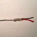
4) I have some wire like below but I'd need more to complete the project.
Any of the above will require a purchase of additional wire.
I've read most of the other threads on twisting heater wiring but most of those addressed AC.
TIA
Dave
My questions are:
1) Should I twist two pairs of 18awg wire and bundle them in some shielded braid? Is shielding needed at all?
2) Is there any need to twist them at all? Could all four wires be just bundled?
3) Should I source some twisted quad wire? (18awg quad is not easily found though)
4) I have some wire like below but I'd need more to complete the project.
Any of the above will require a purchase of additional wire.
I've read most of the other threads on twisting heater wiring but most of those addressed AC.
TIA
Dave
Attachments
I would separately twist the wires for each regulator output.
The #18 wire is large enough, and shielding should not be needed.
The #18 wire is large enough, and shielding should not be needed.
Does the twist pitch make a difference with DC? Would shielding the two pairs together have any negative effect? I have lots of copper braid.I would separately twist the wires for each regulator output.
The #18 wire is large enough, and shielding should not be needed.
Tighter is better, since the regulator output is inductive at HF and is somewhat decoupled from the cable.
Grounded shielding for the filament wires should not hurt, unless the tubes involved are in high impedance circuitry.
If doing this, shield each filament twisted pair separately.
Grounded shielding for the filament wires should not hurt, unless the tubes involved are in high impedance circuitry.
If doing this, shield each filament twisted pair separately.
The reason for twisting AC heater wires is to reduce the varying magnetic field of the heater wires and the hum it may induce in other wire loops. That's not applicable with DC heating.
Nonetheless, it is generally good practice to keep supply wires and their return conductors (for example, ground wires) close together: it reduces the wire inductance and the amount of interference the wires might receive from some other varying magnetic field.
Nonetheless, it is generally good practice to keep supply wires and their return conductors (for example, ground wires) close together: it reduces the wire inductance and the amount of interference the wires might receive from some other varying magnetic field.
Thanks Rayma. Why shield the pairs separately? How would I determine if the circuit has high impedance?Tighter is better, since the regulator output is inductive at HF and is somewhat decoupled from the cable.
Grounded shielding for the filament wires should not hurt, unless the tubes involved are in high impedance circuitry.
If doing this, shield each filament twisted pair separately.
If using high gain 12AX7s, or dual mono, it could be worthwhile. Maybe also some local decoupling.

With a mu of 77, it could be worthwhile to shield the cables separately.
Why use the shelving resistors though, when passive RIAA has the advantage of no HF asymptote.
Also consider a MF resistor instead of the CCS on the output, if you don't need abs max gain,
they can be noisy.
Why use the shelving resistors though, when passive RIAA has the advantage of no HF asymptote.
Also consider a MF resistor instead of the CCS on the output, if you don't need abs max gain,
they can be noisy.
I'm interested in why individual shielding is preferable over just shielding the twisted pair bundles? Not trying to be difficult - just trying to understand.With a mu of 77, it could be worthwhile to shield the cables separately.
Why use the shelving resistors though, when passive RIAA has the advantage of no HF asymptote.
Also consider a MF resistor instead of the CCS on the output, if you don't need abs max gain,
they can be noisy.
Can you expand on the shelving resistors vs passive RIAA?
These topics are way above my pay grade.
The RIAA curve is defined as (approx) a ~50Hz pole (3180uS), a ~500Hz zero (318uS), and a ~2kHz pole (75uS).
This means that the equalized HF response should continuously fall to zero at a rate of 20dB/decade.
So there is no defined shelf where the HF gain becomes constant. In your RIAA, the 80R resistor causes a HF shelf.
Some argue that a HF shelf compensates for cutter head response, etc. but this is not so.
Dual mono construction is good in general , and two separate shielded heater strings is part of that.
Do the shields need to be insulated along their lengths for that? In other words can the shields touch without issues?The RIAA curve is defined as (approx) a ~50Hz pole (3180uS), a ~500Hz zero (318uS), and a ~2kHz pole (75uS).
This means that the equalized HF response should continuously fall to zero at a rate of 20dB/decade.
So there is no defined shelf where the HF gain becomes constant. In your RIAA, the 80R resistor causes a HF shelf.
Some argue that a HF shelf compensates for cutter head response, etc. but this is not so.
Dual mono construction is good in general , and two separate shielded heater strings is part of that.
Shields should terminate directly to the chassis, not to circuit grounds.
They are actually an extension of the chassis. If they are connected at both ends,
there is a possibility of ground loops through the safety ground wiring.
They are actually an extension of the chassis. If they are connected at both ends,
there is a possibility of ground loops through the safety ground wiring.
Planning on the above. Will ground only in the PS chassis. Same applies for the B+/B- umbilical I assume?

Also twisted cables are physically stronger cables than untwisted. It might not be important here but in general, twisting brings strength for free, well almost free due to the slight length reduction. They are also less likely to separate causing open loops that get caught on everything that can possibly be in the way.
- Home
- Design & Build
- Construction Tips
- Umbilical for DC Heaters?