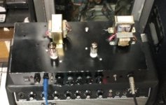
Hi, I'm new to this forum. I build this little amp with the power output in the milliwatt range and I would love you opinion. Is based in 3 projects. The Alembic Preamp, The Real McTube Power Supply, and an idea from a guy named Kris Slyka where he use a Chinese pentode (6j1) as output (https://hackaday.io/project/177987-the-milli-amp), but he settled for low Voltage (24V) I put his idea on steroid and I increased the Voltage to 120V. It works, the sound is perfect for midnight tones and for me sound louder for what it is. What are you opinions? what would you change? Thanks for your time.
EDIT 07/14/2022.
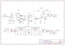
This are the latest changes, thanks for your help.
-Negative Feedback point was changed (like a vibrochamp).
-Negative feedback resistor was reduced to 2.7k.
-Master Vol was entirely removed
-First transformer was reduced from 18VAC to 12VAC.
-Cathode Resistor of 220 was added.
-Grid leak Resistor was increased to 470k.
-Tone stack mistake was fixed (100k resistor)
-Speaker was grounded.
-Capacitance before 7812 was increased (100u)
UPDATE 07/18/2022.
-Clean Headroom was measured to be 0.15W

EDIT 07/14/2022.
This are the latest changes, thanks for your help.
-Negative Feedback point was changed (like a vibrochamp).
-Negative feedback resistor was reduced to 2.7k.
-Master Vol was entirely removed
-First transformer was reduced from 18VAC to 12VAC.
-Cathode Resistor of 220 was added.
-Grid leak Resistor was increased to 470k.
-Tone stack mistake was fixed (100k resistor)
-Speaker was grounded.
-Capacitance before 7812 was increased (100u)
UPDATE 07/18/2022.
-Clean Headroom was measured to be 0.15W
Attachments
Last edited:
Well you can get rid of the coupling cap and grid leak resistor after the master volume control, and the 1M in parallel with it. They aren't doing anything useful. And the NFB is connected to the wrong point, an AC ground. It cannot work. You need 100R under the 1k5 cathode resistor, and connect it to that junction, and the bypass cap should only bypass the 1k5, not the 100R.
Last edited:
Running 18V into a 12V winding isn't a good idea - these transformers are made without a surplus gram of copper or iron and it will saturate - both transformers will likely run hot. A higher voltage secondary (used as primary) for less step-up and a voltage doubler would be better. I'd add a cathode resistor to the 6J1 so that I can see how much current it's drawing. You can also measure it at the 100 Ohm supply resistor, but I prefer a low-voltage point.

And 33K is far too high for the feedback resistor. It should be more like 5-10K, but you will have to experiment.
OK I did the proposed changes, but I could not remove the 100k after the master volume, the amp hum like crazy without doing any guitar sounds.Well you can get rid of the coupling cap and grid leak resistor after the master volume control, and the 1M in parallel with it. They aren't doing anything useful. And the NFB is connected to the wrong point, an AC ground. It cannot work. You need 100R under the 1k5 cathode resistor, and connect it to that junction, and the bypass cap should only bypass the 1k5, not the 100R.
Attachments
Hi, The real Mctube use two 12VAC transformers back to back, I can change the 18VAC Transformer for a 12VAC transformer to be more like the mctube for 170VDC instead of 250VDC.Running 18V into a 12V winding isn't a good idea - these transformers are made without a surplus gram of copper or iron and it will saturate - both transformers will likely run hot. A higher voltage secondary (used as primary) for less step-up and a voltage doubler would be better. I'd add a cathode resistor to the 6J1 so that I can see how much current it's drawing. You can also measure it at the 100 Ohm supply resistor, but I prefer a low-voltage point.
On further consideration I would get rid of the master volume control. All it can do is fight with the NFB. So retain the grid leak resistor, which I would raise to 470k.
Hi, I did all your proposed changes, You were very helpful, now the amp Sound Cleaner and louder. there is more clean headroom. I have a question, now the Pentode is glowing a little blue. Is this normal? Something like this:

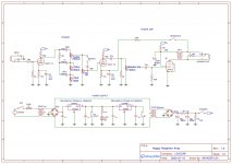
This is the schematic with the latest changes, I'm very thankful for your help.

This is the schematic with the latest changes, I'm very thankful for your help.
150V and 1.8V. I put another 6j1 and the second Tube do not Glow blue.What are the voltages at plate and cathode of the pentode?
So the first one is faulty. I would encourage experimenting with the 100R cathode resistor, by increasing it, 150, 220, ...
No, as stated blue glow ON the glass is actually a sign of a decent vacuum and some harmless cobalt impurities in the glass. Blue, purple or pink glow INSIDE the plate structure around the elements is the sign of a poor vacuum and a possible tube runaway in the future. An orange or red glow on the metal plate itself is an indication that the tube is being overloaded and it will have a short life.So the first one is faulty. I would encourage experimenting with the 100R cathode resistor, by increasing it, 150, 220, ...
The metal case of all controls should be grounded. The ground connection is usually made through the front panel if a grounded metal input jack is mounted on the same panel. If not, run a wire from the case of the volume pot to ground. The hum can be caused by oscillation especially if it appears around mid volume to full volume and vanishes suddenly as the pot is turned down. The 100K resistor from grid to ground lowers the impedance of the grid circuit helping to kill any oscillation. It will also help kill scratchiness in the pot since there will always be some small current flow in a grid circuit due to imperfections in the tube.The hum suggests that the master volume pot isn't grounded.
No, as stated blue glow ON the glass is actually a sign of a decent vacuum and some harmless cobalt impurities in the glass. Blue, purple or pink glow INSIDE the plate structure around the elements is the sign of a poor vacuum and a possible tube runaway in the future. An orange or red glow on the metal plate itself is an indication that the tube is being overloaded and it will have a short life.
The metal case of all controls should be grounded. The ground connection is usually made through the front panel if a grounded metal input jack is mounted on the same panel. If not, run a wire from the case of the volume pot to ground. The hum can be caused by oscillation especially if it appears around mid volume to full volume and vanishes suddenly as the pot is turned down. The 100K resistor from grid to ground lowers the impedance of the grid circuit helping to kill any oscillation. It will also help kill scratchiness in the pot since there will always be some small current flow in a grid circuit due to imperfections in the tube.
Master Volume was entirely removed, so there is not a problem anymore.
- Home
- Live Sound
- Instruments and Amps
- Very little Wattage Guitar Tube Amp. Opinion.