Yes and i dont know why 😅You can't just connect the two outputs. They will fight each other.
If you want somehow to sum two inputs, it's more involving.
I get the impression you're somehow emotionally driven to use that 2nd opamp no matter what?
Jan

Ye i will probably let it go but if i want to add RCA input can i do this? >>>Ha - just let it go!!!
If you don't mind a 6dB loss on both inputs. Of course you could double
the gain on both opamps but the price for that is reduced headroom. Is
that OK?
G²
the gain on both opamps but the price for that is reduced headroom. Is
that OK?
G²
And is there some way to do it better?If you don't mind a 6dB loss on both inputs. Of course you could double
the gain on both opamps but the price for that is reduced headroom. Is
that OK?
G²
Do what Jan suggested and tie off ('+' input to gnd and '-' input to output)And is there some way to do it better?
the second amp. I do that in some designs because it's easy and cheap.
🙂 Stop now. You are in danger of moving from an emotionally driven to use that other half of the 5532 to being pathological! If you want both balanced and unbalanced inputs that is easily done with just a single opamp. Have a look at Douglas Self's small signal book.
ok ok i'm stopping 😂😂 Thanks guys for help, hopefully I can figure it out on my own now 😉🙂 Stop now. You are in danger of moving from an emotionally driven to use that other half of the 5532 to being pathological! If you want both balanced and unbalanced inputs that is easily done with just a single opamp. Have a look at Douglas Self's small signal book.
No way it is that easy, thank you very much 😉Here you go - its like this ...(low tech drafting!).
View attachment 1071660
None yet because im designing itWhat amp are you using?
Another reason why this would be a bad idea: each opamp sees 440R load, which will greatly increase distortion.Ye i will probably let it go but if i want to add RCA input can i do this? >>>
View attachment 1071644
Jan
Once your getting to about 50K with a op amp feedback resistor your starting to get a bit of feedback phase shift caused by resistor and op amp input capacitance.
I tend to put a few pf across feedback resistor to tame it.
Got caught out with transistor matcher I designed. I was getting some oscillation on output with 100k feedback resistor.
A cap fixed it.
I tend to put a few pf across feedback resistor to tame it.
Got caught out with transistor matcher I designed. I was getting some oscillation on output with 100k feedback resistor.
A cap fixed it.
There is plenty of information out there.
Small signal audio design by Douglas Self has whole chapter on balanced line inputs. And if I'm correct, it is free on their website.
Another source of great information is this article called The G word by Bruno Putzey.
You may also look at THAT1200 datasheet that has really great information on balanced connections and CMRR.
What sound card are you using? Is it straight from the motherboard? maybe better solution would be to use external DAC? Just brainstorming ideas, not sure what setup you have in mind.
What amplifier are you using? Does it have balanced interconnections?
You don't really need RCA input - you can just make RCA to XLR cable adapter.
For balanced input you could make instrumentation amplifier - and configure Rg resistor to act as gain by using log pot.
Last edited:
Hello guys, may you be able to help me following case:
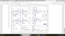
I still have your Legato 3.1 I/V stage from TwisteadPearAudio working in my system. It is both ballanced and SE output stage.
Documentation says:
"Gain of balanced and single-ended outputs can be set independently to match your application"
Schematic:
http://www.twistedpearaudio.com/docs/linestages/legato_3.1_schematic.pdf
I want to change gain only on SE outputs.
Could please tell then which resistor I need to change to what value in case I want change gain to lets say 5x (14dB) only on SE outputs?
According to documentation VR3 & VR4 are used to nullfy DC offset.
http://www.twistedpearaudio.com/docs/linestages/legato_user_manual_3.1.0.pdf
So it must be something different.
http://www.twistedpearaudio.com/docs/linestages/legato_user_manual_3.1.0.pdf
So it must be something different.
Looking at the schematic, VR3 and VR4 appear to be gain until you look closely and see that their slider is grounded. So, they are the 2nd offset pots. I see no gain adjustment? It looks like there will be DC offset on both the "balanced" in and out.

Attachments
Last edited:
Interesting, yes you are right, with the wiper to a DC voltage it controls the offset. Funny thing is that in this type of circuit (instrumentation amp), the value of VR3 and VR4 set the gain. So you would set the gain by the resistance between the two opamp input pins.
Just try it with, say 2.2k between these two points, you will see an ~12dB increase in gain. But you prpobably need to then re-trim those VR's for zero DC offset.
Alternatively, maybe easier, change R21, R23. The R21/R17 and R23/R19 ratio set the gain of the compound output stage.
.
Jan
Just try it with, say 2.2k between these two points, you will see an ~12dB increase in gain. But you prpobably need to then re-trim those VR's for zero DC offset.
Alternatively, maybe easier, change R21, R23. The R21/R17 and R23/R19 ratio set the gain of the compound output stage.
.
Jan
- Home
- Amplifiers
- Chip Amps
- opamp gain control