Need a bit of help with an Xtant x604.
Right rear channel burning resistors
does anyone have a schematic for the amp by chance ? Should component values be the same on all 4 of the output sections ?
r919 and r911 where burnt up ,

The bf422 transistor is showing a non solid ohm reading between the left and right leg , unlike every other bf422 on the board
when I replaced the two resistors they started smoking again , audio was playing with the Burt up resistors , with distorted 1.2v dc offset on the terminal
Right rear channel burning resistors
does anyone have a schematic for the amp by chance ? Should component values be the same on all 4 of the output sections ?
r919 and r911 where burnt up ,
The bf422 transistor is showing a non solid ohm reading between the left and right leg , unlike every other bf422 on the board
when I replaced the two resistors they started smoking again , audio was playing with the Burt up resistors , with distorted 1.2v dc offset on the terminal
Damn the r911 was 101 1k not 103 10k, I also found r917 burnt out (cracked in half) .I found new bf422’s different badging hopefully the right ones , I haven’t removed any of the “good ones” yet to test out of circuit . On the questionable one I can’t get a solid ohm reading it’s all over the place like the burnt/cracked resistors where, also finding it super difficult to trace what may have caused it , and the circuit board traces are all over the place
Last edited:
Just took out another bf423 and tested , they seem similar in readings , however if I probe the board location for q910 right and leftHow does the transistor reading compare, out of the circuit, to the other transistors with the same part number?
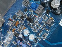
The image attached is from a 604.
Pins the resistance instead of hitting a solid 1k ohms , the meter starts at 2k ohms over a 10 second period will climb to 30k ohms then will stabilize at 20k ohms after 15 seconds . No other output sections do this , all the other bf422 locations on the board read 1k ohms on the the board weather the transistor is in or out immediately.
Q909 happened to be the second one I took out. These are the readings from them in a tester . They aren’t matching at all.Are you using the same probe orientation for each transistor location?
Is Q909 OK?
Attachments
Then if I test the transistors in diode mode in or out of circuit the appear to be matching and functioning. So I’m stumped as to what could be doing this , any ideas on what else would burn up all these resistors. I’m also not sure what the hfe is testing with different readings , when in diode mode with the tests show the standard .6v or so for e and c probe 2 on b
Another thing to note is the trace that goes from r911 to q911 got hot enough to burn the coating off the trace however there is zero resistance still from component to component and q911 still tests like the others.
Reinstalled q909 and q910, when I test them in circuit in diode mode they show 1.1v and 2v vs the .6v out of circuit , the other channels read .60v in or out
Did you check Q907?
The hfe is the DC current gain. The number can vary quite a bit between transistors of the same part number, especially for older transistors or transistors from a different batch.
The hfe is the DC current gain. The number can vary quite a bit between transistors of the same part number, especially for older transistors or transistors from a different batch.
Yea it’s seems to match the others however there is a trace under the r911 coming from the q908 and I can’t find a continuity point for it , is that trace supposed to connect to a side of the r911 because currently it’s not
Here’s where I’m at ,when everything is in circuit the q911 to r907 trace burns up, when that happens there is some clicking (arking) noises coming from the power supply fet area , and if I play audio though this circuit with those components removed it actually plays audio through it , but after a 10 seconds same thing , noise from the power supply fet area . Are there individual transistors for each channel in the power supply circuit ? You would assume it would through it into overcurrent protection if there was an issue . I was almost going to give up and simply disable the right rear channel entirely and run 3 channel with the rears in parallel on the left @2ohm since the fronts are already 2ohm x2.
Q907 and R911 both seem to test fine out of circuit 🤷♂️
This Appears to be a common problem too because there is a x604 on eBay right now for parts That has the same exact components burnt out in a more dramatic way
that amp also has visable power supply damage
Last edited:

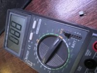
On your driver power supply, how do the voltages compare to the ones in the attached image?
Seems in order ( components still removed from channel) no audio connected , idle current 3.26 amps@ 12v 39watt draw shown on the bench supply
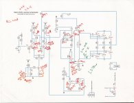
This partial diagram has designations for the 604 in red. Are the connections for R911 and Q907 correct? If so, I don't see how it could burn a trace if the current has to pass through a 100 ohm resistor.
Is it possible that the board has become conductive?
Is it possible that the board has become conductive?
Attachments
This partial diagram has designations for the 604 in red. Are the connections for R911 and Q907 correct? If so, I don't see how it could burn a trace if the current has to pass through a 100 ohm resistor.
Is it possible that the board has become conductive?
min unsure on that , there don’t seem to be any noThis partial diagram has designations for the 604 in red. Are the connections for R911 and Q907 correct? If so, I don't see how it could burn a trace if the current has to pass through a 100 ohm resistor.
Is it possible that the board has become conductive?
These connections are correct , so I reconnected everything with new resistors to try to recreate the original failure , powers up fine then a second later R917 stars smoking 🤷♂️This partial diagram has designations for the 604 in red. Are the connections for R911 and Q907 correct? If so, I don't see how it could burn a trace if the current has to pass through a 100 ohm resistor.
Is it possible that the board has become conductive?
May have found the culprit in diode test mode , q811 is showing .7v and .7v on q811. And for one on question q911 .28v and 2.6v .
that’s not good right
also what alternate part number would it be

that’s not good right
also what alternate part number would it be
Last edited:
Thanks , definitely think this was the problem , when I removed the q911 SMDBC856B no more smoking , and all those odd readings on q910 while in circuit match the others. Won’t know for sure until a replacement transistors arrive if there was something else’s that made q911 fail
also would you happen to know the bias adjustment mA spec , and method of testing for this amp?
also would you happen to know the bias adjustment mA spec , and method of testing for this amp?
- Home
- General Interest
- Car Audio
- Xtant X604 repair help