Hi,
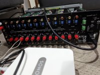
I've owned a Sonance Sonamp 1230 amplifier for over a decade. It has 12 channels and I use 8 of them to power 8 in-ceiling speakers. For the input, I have 2 Sonos Connect: One that powers 6 speakers on the "bus input" and the other Sonos Connect that powers the last 2 speakers (channels left and right) in "direct" configuration. This has been working fine for many years, but lately it stopped working. Most of the time. After some debugging, here are my conclusions:
1- The fuse is fine (checked for continuity with a DMM)
2- The auto-trigger isn't the issue (I tried the bypass mode as well as "external voltage" hooked to a 9v battery)
3- I don't see any blown capacitor, but I am aware that bad capacitors are not always blown
4- I tried other speakers and it didn't fix the problem
5- I tested that my Sonos Connect works on another amplifier and I tried another Sonos Connect on this amplifier: The problem remains with the amplifier
6- The red "AC ON" LED is turned on and the green "Active" LED is turned on when the power button is pressed
7- I tried my tests using only one channel, unplugging all other speakers, both on the "bus input" and the "direct input" and the same problem is present.
One thing to note with this amplifier: When you power is on, the amber LEDs labelled "protection" will turn yellow for a few seconds, and then turn off. This is absolutely normal, as stated in the user manual:
"Each time the amplifier is initially plugged in and the main power switch is turned on, the protection LEDs will light for approximately 3 seconds while amplifier circuitry is stabilizing. This prevents spikes and thumps from getting to speakers. Any time the protection circuits are triggered, turn the main power switch off before troubleshooting for shorted output connections or faults with source components."
So this is what I noticed: After leaving the amplifier UNPLUGGED (perhaps depressing the power button has the same effect?) for many hours (last night I waited 20 hours, but perhaps 1h is enough?) when I power up the amplifier, it does the above mentionned routine and will work fine. But as soon as I power it off (no need to unplug), for example after only 1 minute, if I try again to power it on, the amplifier will NOT do the yellow LED protection (accompanied with a click click) and then it won't play any music.
It is as if once the music stops, it needs to wait for a few hours do be able to work. But once it starts, it can play for hours.
Any suggestions as to what could be wrong or how I can debug further this problem?
Please see attached pictures.
Attachments


Edit: I left it unplugged for 1 hour and this was enough to "reset" the problem. Next I'll try to simply leave it "off" (but plugged) for an hour if it also fixes the issue.
Change all the electrolytic caps in the protection circuit, they are going bad.
There must be a time based circuit for protection mode, check with a stopwatch (or app).
The time constant is usually off a capacitor decay, using a cap + resistor. The cap is the most likely culprit, as the unit is more than ten years old.
Keep the unit in a ventilated area, and think of checking all the caps with a meter, they are quite cheap, look for graphic type capacitance meter.
Thank you for your reply. A few questions:
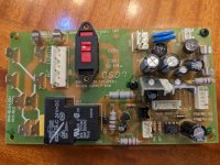
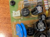
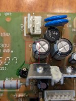
1- There are MANY capacitors here. I'm assuming that I should focus on the one for the "main board" (picture #3) and not worry about the 6 circuit boards for each pair of channels?
2- What exactly should I be checking with a stopwatch?
3- Can I check the capacitors without unsoldering them from the board?
Thanks
Look for supplies to relays, and trace that, delay is for speaker relays.
Hopefully off a single timer circuit, using a capacitor, though could be timer IC, which is unlikely.
Hopefully off a single timer circuit, using a capacitor, though could be timer IC, which is unlikely.
1. Capacitor for muting relay.
2. Check time with a stopwatch, if it is supposed to be 3 seconds, and goes beyond 5, change the capacitor and the resistor. And if there is a transistor to switch the relays, check that as well.
3. Checking capacitors in circuit is possible with a scope, otherwise no.
Find the circuit diagram, (schematic), should be obvious what is to be checked from that.
Thank you for the reply. It actually isn't 3 seconds. I would guess it is closer to 1 second. Do you have an idea of where I could look for schematics...? Are there specialised forums for that?
Google is your friend...some sites require (free) registration, hifiengine, elektrotanya, some Russian sites, among others are known for their large collections.
Can't be too difficult.
Another way is to search using the output devices, most circuits are common to many amp makers.
Can't be too difficult.
Another way is to search using the output devices, most circuits are common to many amp makers.
Thanks. I searched both sites and didn't find them. I did try Google but also no luck. I already have the user manual but it doesn't include the circuit schematics.
I wanted to disassemble the circuit boards to see if I could find the "name" of the sub circuits printed on them, but each screw has been glued in place so for the time being I'll try and see if I can find alternative.
If you ever come accross the schematics on those Russian sites, please do let me know, it would be very much appreciated.

I won't lie. I'm a computer engineer and all the electronics courses are way far behind me. I don't fully understand your suggestions.2SC2837 and 2SA1186 are the outputs.
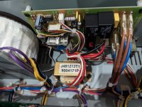
This being said, now the amp won't do the circuitry is stabilizing routine at all, even if I wait for 12 hours. No more music. I disassembled the main board and here are some pictures.
I tested both fuses for continuity.
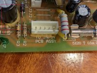
Most of the resistor seemed to have a paste at their bottom, which led me to believe they leaked, but I now think this is glue since most of the connectors also have this glue.
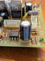
There is a resistor that has a brown goo stuck in the glue (see the last picture) but reading the resistance I could clearly read 39k Ohms, so this is possibly just soldering paste (?).
Attachments
-
 PXL_20220706_233126965.jpg470.9 KB · Views: 110
 -
 PXL_20220706_233139494.jpg392 KB · Views: 108
 -
 PXL_20220706_233225358.jpg403.6 KB · Views: 92
 -
 PXL_20220706_233241754.jpg380.2 KB · Views: 112
 -
 PXL_20220706_233249683.jpg411.8 KB · Views: 104
 -
 PXL_20220706_233321531.jpg370.1 KB · Views: 98
 -
 PXL_20220706_233443448.jpg362.4 KB · Views: 95
 -
 PXL_20220706_233456902.jpg428 KB · Views: 91
 -
 PXL_20220706_233708767.jpg415.2 KB · Views: 100
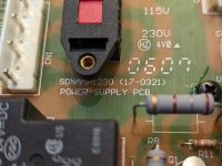
UR6, first photo.
That is a thermal relay, replace it, date codes are from 2007.
Replace C7, and Q1 as well...that is the relay circuit I told you about.
And if the new relay does not start, it is sensing a problem down the line, that is a big repair, above your level.
Put another 39K resistor, high up off the board like the others, the glue has heated and become conductive, maybe long term the resistor got hot. If possible, put one with more watt rating.
Remove as much glue as possible, it goes conductive over time.
Last edited:
Thank you for taking the time to give me detailled information.UR6, first photo.
That is a thermal relay, replace it, date codes are from 2007.
Replace C7, and Q1 as well...that is the relay circuit I told you about.
And if the new relay does not start, it is sensing a problem down the line, that is a big repair, above your level.
Put another 39K resistor, high up off the board like the others, the glue has heated and become conductive, maybe long term the resistor got hot. If possible, put one with more watt rating.
Remove as much glue as possible, it goes conductive over time.
When you say to put "another 39k resistor", you mean in replacement of resistor R6 - the one that had brown goo? Or you mean ADDING a resistor? And you meant to have it high up smilar to R8 or R12, so that it is farther away from the PCB. correct?
To remove the glue, should I use sand paper, or a sharp knife?
Thanks again. I will absolutely report back here.
- Home
- Amplifiers
- Solid State
- Sonance Sonamp 1230 intermittently not playing music