I'm new to designing with tubes, and have just built and tested my first project, a P-P amplifier using a pair of 2E26 beam power tubes. The datasheet indicates that a class AB2 audio amplifier can achieve 40W or 50W output depending on the anode supply voltage, and output transformer impedance. I chose the more conservative 40W.
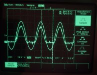
Although the amplifier works and sounds nice to my ears, I am having trouble understanding why I can't achieve more than 32W output before there is clipping. When I probe both the output voltage and the cathode current, you can see from the scope screenshots that the output is clipping, but the current into the transformer still appears sinusoidal.
This looks like saturation in the output transformer, no? Initially I was using an Antek 40W toroid with 6.6K primary, so I figured I would try an Edcor 50W with the same winding ratios, and hopefully the problem would go away. The new transformer made no difference!
After studying the signals for a while, I noticed the output signal was asymmetrical. I figured this was causing a DC current to run through the primary. The lopsided waveform turned out to be distortion from the pentode amplifier, which I replaced with a different circuit using a current source for bias (not shown in attached schematic). Although there is now much less distortion (2nd harmonic 40db down), the clipping remains.
I've adjusted the bias so there is 20mA idle current, as specified in the datasheet.
I'm testing the amplifier using a resistor load, and verified that its value is 8 Ohms. I'm measuring the RMS voltage on the output with a Fluke meter.
I'm thinking there might be something obvious that I'm missing. Any ideas?
2E26 Datasheet
Attachments
Saturation only occurs at low frequencies; core flux decreases as frequency increases. In the midband (400-1000 Hz), the magnetizing current is negligible. Cathode current won't be sinosooidal in an AB amp, as each tube is cut off for part of the cycle - the other tube has to conduct considerably more, which it will - look at the curves.
Two data sheet "gotchas" - first, regulated voltage is assumed, so if your supply drops at full output, the output will be correspondingly less. Also, it doesn't include transformer losses - most audio transformers are in the 90% efficiency range.
Two data sheet "gotchas" - first, regulated voltage is assumed, so if your supply drops at full output, the output will be correspondingly less. Also, it doesn't include transformer losses - most audio transformers are in the 90% efficiency range.
I agree, the fact is transformers are not lossless.
Example:
A 5k to 8 Ohm push pull has primary DCR of 250 Ohms, and secondary DCR of 0.4 Ohms.
(DCRs that are about 5% of the winding impedance),
Therefore . . .
The DCR loss of the primary is 0.5dB, and the DCR loss of the secondary is 0.5 dB.
The total loss is 0.5dB + 0.5dB = 1dB.
A 1 dB loss gives 0.89 of the voltage (11% voltage loss).
Power goes to the square of the voltage.
1 dB loss is 0.792 of the power. 1 / 0.792 = 1.26
Power / 1.26 = a 1 dB loss
40 Watts / 1.25 = 31.7 Watts.
Last edited:

Lots of spikes on those scope traces. Is something going into oscillation? Measure the grid voltages of the driver stages without a signal. Usually asymmetrical sines like that mean something is running out of headroom. It can't swing enough voltage.
Wow, thanks for the replies!
Forgot to mention the power supplies are regulated, zener diodes with power MOSFETs for series pass devices. There's only 100mV of sag on the 400V at full power.
I had a feeling I was being naive about something. Hadn't considered transformer Ohmic losses at all. That makes perfect sense. I measured resistances on one of them, and they were indeed almost exactly 5% of the rated impedances. Explains everything perfectly, including why the bigger transformer wasn't helping.
I tried raising the B+ voltage to 430V, and the G2 voltage to 150V, and lo and behold, I get 40W of output at the load! So the tubes must be producing something like 50W of power to get this much at the load. I won't say it's anything like a pure sinewave when the G1 voltage is positive, but at least not clipping. Understood this is the major issue with AB2. I may try MOSFET source followers in place of the 6CL6s drivers.
Yes, there is brief transient HF oscillation at the exact time that the clipping starts, and where it stops. The amplifier has been stable whenever it is not clipping. I don't understand that yet, but not too worried about it.
Your oscilloscope traces of the cathode current, channel 2, looks like you might have had your scope on AC coupling.
But if it is AC coupled, you can guess the approximate current versus time because:
For push pull Class AB2, the cathode current should rise from the quiescent current to a peak current, and then fall down through the quiescent current value, and keep falling further all the way to 0 current (the flat part of the channel 2 trace).
That kind of trace of cathode current is the same shape as a class AB1 output stage (AB1 no grid current, AB2 with grid current during part of the cycle).
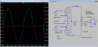
I think clipping occurred due to plate voltage swing is being limited by HT supply. Increased HT to 500V, increased cathode res to 10 ohms, and increased bias to keep out max. dissipation allowed, but still exceed max. plate voltage allowed(?).
Attachments
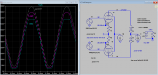
Note that trimpot R17 is superflouos. As you have a Concertina phase inverter, and both cathode and plate restistors already have low tolerances, both output signals are identical (besides phase, of course) with negligible aberrations.
Best regards!
Best regards!
Your biasing arrangement is unconventional to say the least - you have -150V on the volume pot, and are exceeding V1 max heater-cathode voltage rating. Would be better without the bipolar supply for the front end (just use that for the cathode followers).
on first photo the cathode show that the amp is in AB class leaving the class A.I'm new to designing with tubes, and have just built and tested my first project, a P-P amplifier using a pair of 2E26 beam power tubes. The datasheet indicates that a class AB2 audio amplifier can achieve 40W or 50W output depending on the anode supply voltage, and output transformer impedance. I chose the more conservative 40W.
Although the amplifier works and sounds nice to my ears, I am having trouble understanding why I can't achieve more than 32W output before there is clipping. When I probe both the output voltage and the cathode current, you can see from the scope screenshots that the output is clipping, but the current into the transformer still appears sinusoidal.
This looks like saturation in the output transformer, no? Initially I was using an Antek 40W toroid with 6.6K primary, so I figured I would try an Edcor 50W with the same winding ratios, and hopefully the problem would go away. The new transformer made no difference!
After studying the signals for a while, I noticed the output signal was asymmetrical. I figured this was causing a DC current to run through the primary. The lopsided waveform turned out to be distortion from the pentode amplifier, which I replaced with a different circuit using a current source for bias (not shown in attached schematic). Although there is now much less distortion (2nd harmonic 40db down), the clipping remains.
I've adjusted the bias so there is 20mA idle current, as specified in the datasheet.
I'm testing the amplifier using a resistor load, and verified that its value is 8 Ohms. I'm measuring the RMS voltage on the output with a Fluke meter.
I'm thinking there might be something obvious that I'm missing. Any ideas?
2E26 Datasheet
If you start from a low lwvel you can see, monitoring the cathode current, when it start to leave class A; the level of how it stay in class A depend from Ibias of the output stage.
You can check also the sister tube of the amp
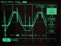
In the second photo it is possible to see that the clippng is simmetric ( almost) so the amp iw owrkin fine.
The only additional thing is to disconnect the feedback loop and check the phase splitter if it goes clipping , it is possible that some issue is from this circuit.
In every case you can low the Ibias of output stage (= more negative grid) so the driver stage can work in a more negative range.
Walter
Let us try and be accurate in our statements:
The cathode current goes to zero when the Sum of 'the negative grid bias volts' and the 'negative swing of the signal',
are negative enough to take the tube into cutoff.
Just one way to think of it.
The quiescent cathode current is dependent on how more negative the grid voltage is than the cathode voltage.
Generally, The grid bias Voltage sets the cathode current.
The cathode current does not set the bias Voltage (that would be the Cart pulling the Horse).
There are special cases, Shishido designed amplifiers that have positive quiescent grid current. That is a different universe, and a genius idea.
Just my opinions.
Last edited:
But that is quiteThe cathode current does not set the bias Voltage (that would be the Cart pulling the Horse).
https://www.google.com/books/editio...of_the_Me/R8nVAAAAMAAJ?hl=en&gbpv=1&bsq=horse


I totally agree, and that is one of the things I am planning to change soon; this is just a snapshot of what I have today. It looks like 150V is plenty of supply for a pentode voltage amplifier with enough gain for the job, and I'll feel much better about not having 150V across the input cap!Your biasing arrangement is unconventional to say the least - you have -150V on the volume pot, and are exceeding V1 max heater-cathode voltage rating. Would be better without the bipolar supply for the front end (just use that for the cathode followers).
What if the gm of the output tubes is mismatched? Wouldn't this trimpot allow one to compensate for this?Note that trimpot R17 is superflouos. As you have a Concertina phase inverter, and both cathode and plate restistors already have low tolerances, both output signals are identical (besides phase, of course) with negligible aberrations.
Yes, after a few of the earliest posts here, I discovered this to be the case last night, achieving my design goal of 40W output to the 8 Ohm load by generating ~50W from the output tubes, by increasing the plate voltage a mere 30V, and increasing the G2 to 150V.I think clipping occurred due to plate voltage swing is being limited by HT supply. Increased HT to 500V, increased cathode res to 10 ohms, and increased bias to keep out max. dissipation allowed, but still exceed max. plate voltage allowed(?).
Originally I would have agreed that 500V exceeds the tube's maximum ratings, but look at the datasheet at the link I gave in the initial post. It includes pages from different editions (they are dated in the page footer). If you scroll down, you'll find the 1960 edition, and RCA revised the maximum plate voltage allowed for the CCS AB2 design to be 600V.
This brought to light something else I hadn't seen before--specifications are also given in the 1960 edition for a 40W/50W AB1 amplifier as well. I may try this, as the distortion should be much lower, although it will mean a whole new set of transformers, and some other design changes (including removal of the driver tubes).
By the way, where did you find a SPICE model for a 2E26? If the model is accurate, that would save me a lot of aggravation!
https://www.diyaudio.com/community/threads/vacuum-tube-spice-models.243950/post-6307851
Using Google search or search Spice model forum using ".subckt 2e26" bring you there.
Using Google search or search Spice model forum using ".subckt 2e26" bring you there.
I'm new to designing with tubes, and have just built and tested my first project, a P-P amplifier using a pair of 2E26 beam power tubes. The datasheet indicates that a class AB2 audio amplifier can achieve 40W or 50W output depending on the anode supply voltage, and output transformer impedance. I chose the more conservative 40W.
Although the amplifier works and sounds nice to my ears, I am having trouble understanding why I can't achieve more than 32W output before there is clipping. When I probe both the output voltage and the cathode current, you can see from the scope screenshots that the output is clipping, but the current into the transformer still appears sinusoidal.
This looks like saturation in the output transformer, no? Initially I was using an Antek 40W toroid with 6.6K primary, so I figured I would try an Edcor 50W with the same winding ratios, and hopefully the problem would go away. The new transformer made no difference!
After studying the signals for a while, I noticed the output signal was asymmetrical. I figured this was causing a DC current to run through the primary. The lopsided waveform turned out to be distortion from the pentode amplifier, which I replaced with a different circuit using a current source for bias (not shown in attached schematic). Although there is now much less distortion (2nd harmonic 40db down), the clipping remains.
I've adjusted the bias so there is 20mA idle current, as specified in the datasheet.
I'm testing the amplifier using a resistor load, and verified that its value is 8 Ohms. I'm measuring the RMS voltage on the output with a Fluke meter.
I'm thinking there might be something obvious that I'm missing. Any ideas?
2E26 Datasheet
The power expected at what THD are declared? 0,5%, 1%, 5%?
Have you measured this? I hope you have a minimum of test set; with a good sound card and attenuator 20dB and 40 dB, with Arta or Visual analyzer sw you can read the THD; is not define it only with a scope
Which is the OT you used? On data sheet it will be 8000 ohm for 500 Vdc
In the photo you sent, as told you, the clipping is symmetric so the stage seems to work well.
And you can check this reading with ac voltmenter the signal come from splitter at different level. In case you can adjust
The voltage on C3 and C4 can be similar for different level and the same for output of the CF on R4 and R18
Same for anode of output tube
This is also a test to understand if the tubes are similar as dynamic specs.
As I wrote the photo of the monitor on cathode of output tube is the AB operation; if you go low on level you can see a perfect sinus that tells you that is class A; this is similar to both cathode.
One more thing, connect one end output of OT trafo to the ground; is better also for security
Yes, probably. The question ist how to determine. I think you'd need an analyzer to adjust the trimpot for as low as possible even order harmonics distortion (or optionally to colour the amps sound, to impose some »sound signature« on it, as some say here).What if the gm of the output tubes is mismatched? Wouldn't this trimpot allow one to compensate for this?
Best regards!
PRR,
Thanks for the picture!
I love it.
Airplanes did that too.
I said: "the cart pulling the horse".
I think in the picture the horse is pushing the cart.
But I could be wrong, a wide angle lens might have shown a horse at the other end of the cart.
That would be Push Pull.
Thanks for the picture!
I love it.
Airplanes did that too.
I said: "the cart pulling the horse".
I think in the picture the horse is pushing the cart.
But I could be wrong, a wide angle lens might have shown a horse at the other end of the cart.
That would be Push Pull.
- Home
- Amplifiers
- Tubes / Valves
- Class AB2 Amplifier Clipping. Why?