Those aluminum angles are just an intermediary and are meant to be bolted to a larger aluminum heatsink or suitable aluminum chassis.
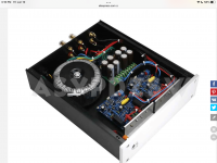
But it is a finished product they are selling, if you look at the 2nd photo. And that is the reason I am asking.
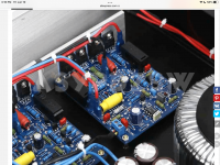
So what version is this? There are 4 transistors vertically mounted to the thin plate heat sink instead of 4 horizontally to a intermediary heatsink as you mentioned then onto the larger case heat sink.
It's a 405-I. LM301 opamp, no thin-film current limiter, no clamp circuit. Two of those transistors are drivers, the other two are power transistors. Might be one of the +/-35V versions that only deliver 67W mentioned above, but even if so the heatsinking isn't adequate.
I think I mentioned above that most 405 clones I have seen have been of the first PCB version. I don't know why these people do that. Quad themselves improved considerably over this version several times. There is no reason for anybody to think this was the best version.
The advertised wording for the eBay one contains several errors such as 'class A dynamic biasing', and you can just remove N1 and N2 in a real 405-2: no need to jumper anything. The one in your picture is a 405-1, given by the current limiting transistors Tr5-6, and doesn't appear even have D13 which is the most important modification of all.
The first attached schematic is what someone else created for the LJM Quad 405-2.
The second attached schematic is the Quad 405 MK2 schematic. (At least what I found online.)
Does that seem right? If so, it has D13 (as labeled in the Quad 405 MK2 schematic) but does not have the diode between the bases of TR9 and TR8 (of the Quad 405 MK2 schematic.)
The second attached schematic is the Quad 405 MK2 schematic. (At least what I found online.)
Does that seem right? If so, it has D13 (as labeled in the Quad 405 MK2 schematic) but does not have the diode between the bases of TR9 and TR8 (of the Quad 405 MK2 schematic.)
Attachments

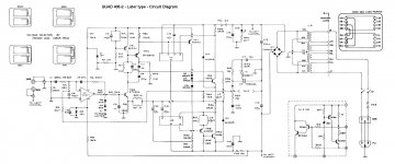
This is the modification I'm talking about. You can see that Quad relabeled D6 as D13 and added a new D6 on the other side of the base of Tr9.
Without N1/2 (instead Tr5/6), or with any PCB earlier than M.12565.5, it is a 405-1, and there were only a few thousand 405-2s built without D13.
Without N1/2 (instead Tr5/6), or with any PCB earlier than M.12565.5, it is a 405-1, and there were only a few thousand 405-2s built without D13.
I will look at the PCB pattern and see if that diode can be added cleanly. How does the circuit operation change with the added diode?
Should TR5/6 be removed even if operation is far from limiting?
Should TR5/6 be removed even if operation is far from limiting?
It's fairly easy to add the diode, but you have to cut a track.
I didn't say anything about removing Tr5/6, and I can't see any reason to do so. You can improve the way they operate: find the Berndt Ludwig paper on the 405. It also tells you why D13 is important, and it is: it reduces THD by 2/3 at high frequencies.
I didn't say anything about removing Tr5/6, and I can't see any reason to do so. You can improve the way they operate: find the Berndt Ludwig paper on the 405. It also tells you why D13 is important, and it is: it reduces THD by 2/3 at high frequencies.
The Bernd Ludwig Quad 405 Upgrade paper is here for anyone else looking for it:
https://www.dadaelectronics.eu/uplo...grade-Instructions-Bernd-Ludwig-V-14-2010.pdf
https://www.dadaelectronics.eu/uplo...grade-Instructions-Bernd-Ludwig-V-14-2010.pdf

Has anyone built this version? https://www.ebay.co.uk/itm/22499061...wsVYo/iizxYx6FUTRGFycJxZQ=|tkp:Bk9SR9rWm_r4YA any problems to be aware off?
As usual with clones, it is based on the 405-1, with the original inferior current limiting, no D13, and no clamp circuit. I don't know why he uses an 80V capacitor in a 6.3V position.
- Home
- Amplifiers
- Solid State
- QUAD 405 clone