The OTL configuration has obvious advantages, but it is not very practical with "regular" tubes and speaker impedances: to push a reasonable output power into a 4 ohm load requires largish currents, huge tubes tolerating amperes of cathode current, meaning they also have a large plate dissipation, and because of the voltages involved in tubes circuits, the output power is also gigantic.
This is not very convenient, and 800 ohm speakers were a niche, limited to some TV sets and record players.
Here is a possibility to fake an OTL, without actually enduring all the consequences. It is not perfect, obviously and requires a transformer, but the topology makes the transformer almost invisible.
The example I provide has been actually tested, but it is not meant to be a complete, finished project: it is improvised with what I had handy, and to make a real, buildable project, you need to do your own work.
Here is the circuit:

The output stage is a cathode-follower, directly driving the load. Of course, the transconductance and the maximum cathode current are too low to drive a regular load. This requires a trick, in the form of a transformer.
The primary of the transformer is in the anode circuit, where it senses the excess current required from the cathode and provides "assistance" via the stepped-down secondary.
Note that it is an actual follower: you could argue that since the same excitation current flows through both windings in series, it is simply an autoformer rearrangement of a conventional plate-loaded stage, but this circuit is always a follower (ideally at least), and even if you alter the turns ratio, it will always tend to a gain of 1.
In practice, with a weakish tube like the ECL82 and a non-optimal transformer, it is rather far from unity gain (much lower), but it does work.
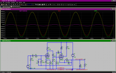
This is the response to a 1K triangle wave, just before clipping:

This is the clipping behavior:

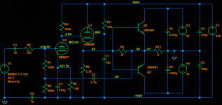
And this is the test circuit:

It is based on the same transformer and heat-sunk PCL82 as this project: https://www.diyaudio.com/community/...rging-a-e-pcl82-amplifier.351667/post-6134055
With 10K in the screen grid, the output power is 4W for 1% THD (Vs=320V, Itot=50mA).
With the auxiliary winding in the grid circuit, the output rises to 5.5W for 1% THD, and the supply current to 60mA .
I also include the .asc, but for reference only: the values have been heavily altered according to the real circuit, and they might not work well in sim
This is not very convenient, and 800 ohm speakers were a niche, limited to some TV sets and record players.
Here is a possibility to fake an OTL, without actually enduring all the consequences. It is not perfect, obviously and requires a transformer, but the topology makes the transformer almost invisible.
The example I provide has been actually tested, but it is not meant to be a complete, finished project: it is improvised with what I had handy, and to make a real, buildable project, you need to do your own work.
Here is the circuit:
The output stage is a cathode-follower, directly driving the load. Of course, the transconductance and the maximum cathode current are too low to drive a regular load. This requires a trick, in the form of a transformer.
The primary of the transformer is in the anode circuit, where it senses the excess current required from the cathode and provides "assistance" via the stepped-down secondary.
Note that it is an actual follower: you could argue that since the same excitation current flows through both windings in series, it is simply an autoformer rearrangement of a conventional plate-loaded stage, but this circuit is always a follower (ideally at least), and even if you alter the turns ratio, it will always tend to a gain of 1.
In practice, with a weakish tube like the ECL82 and a non-optimal transformer, it is rather far from unity gain (much lower), but it does work.
This is the response to a 1K triangle wave, just before clipping:
This is the clipping behavior:
And this is the test circuit:
It is based on the same transformer and heat-sunk PCL82 as this project: https://www.diyaudio.com/community/...rging-a-e-pcl82-amplifier.351667/post-6134055
With 10K in the screen grid, the output power is 4W for 1% THD (Vs=320V, Itot=50mA).
With the auxiliary winding in the grid circuit, the output rises to 5.5W for 1% THD, and the supply current to 60mA .
I also include the .asc, but for reference only: the values have been heavily altered according to the real circuit, and they might not work well in sim
Attachments
Well... I don´t want to sound sarcastic but I think the rest of us would call it CFB, or cathode feedback? CFB can be an effective way to get the most out of a given tube/OPT combo.
Yes and no: CFB is mostly about feedback, not power. Most of the time, the speaker is not directly tied to the load and even when it is, the main goal is to use a single winding to insert the feedback and drive the speaker.
In the virtual OTL, the tube should do most of the heavy lifting, but as it cannot, it is assisted by a helper winding.
Both concepts might end up with the same implementation, but the design philosophy and goals are different: the OTL eliminates or reduces transformer-related imperfections, like leakage inductance, hysteresis, etc.
And the virtual OTL also has FB, one local and inherent to the topology and a global one too
I must agree with post #2 , its just cathode feedback.
Besides, Claus Byrith done something like that in his EL34 SE amp.
Claus Byrith SE
Besides, Claus Byrith done something like that in his EL34 SE amp.
Claus Byrith SE
OK, things get reinvented all the time. I don't see my version as cathode feedback (although it also does too), but more like a way of replicating OTL properties without the huge tubes.
Many of the CFB circuits only focus on just feedback aspects, use a dedicated winding, and when the winding happens to be common with the FB and speaker, it is mostly for practility and cost reasons, not to bypass the transformer's properties
Many of the CFB circuits only focus on just feedback aspects, use a dedicated winding, and when the winding happens to be common with the FB and speaker, it is mostly for practility and cost reasons, not to bypass the transformer's properties
Hi Elvee,
Your approach looks really interesting. I wonder, could it be used with a push-pull transformer?
Your approach looks really interesting. I wonder, could it be used with a push-pull transformer?
Probably. It would be somewhat tricky, but it should be possible: the connection to the speaker would have to be balanced, with the center-tap of the secondary grounded, and the global feedback connection should ideally be balanced too, meaning most of the amplifier should have a balanced structure, but you could probably get away with a single FB connection taken from one end of the secondary.
Note that with this scheme, you can apply a much larger feedback at high frequencies: the leakage inductance which normally limits the amount of feedback allowed helps isolate the direct cathode connection from the rest of the transformer and now works to your benefit
Note that with this scheme, you can apply a much larger feedback at high frequencies: the leakage inductance which normally limits the amount of feedback allowed helps isolate the direct cathode connection from the rest of the transformer and now works to your benefit
The other option is to fix the OT distortion directly, leaving a standard Amp with OTL sound and tolerable heat.
Distortion in the OT manifests as magnetizing current. (both the normal inductor current, saturation + Hysteresis current ) Which then makes for unwanted voltage drops across the output tube rp and the primary winding resistance. The local N Fdbk can fix the drop across the tube rp, but it doesn't see the winding resistance drop unless you have an auxiliary winding for the feedback source.
The winding resistance drop can be fixed by a positive current referenced Fdbk from a current sampling resistor below the output tube cathode(s). A high value (adjustable initially) Rfdbk resistor from that output cathode back to the associated driver cathode (above a low value R in the driver cathode) provides extra drive to the driver tube to compensate for the loss of voltage across the winding resistance for the current seen. Effectively nulling out the resistive V drop from magnetizing current and signal current as well ( Rfdbk adjusted to do so ), so that the V drop does not get passed on to the secondary. (loss + compensation boost = 0 ) Negative resistance essentially. It will also significantly improve the damping factor by removing the primary winding resistance. Audio Precision patent # US4614914 1986 by Bruce Hofer, as pointed out by Merlin a couple of years ago. Also, RDH4 page 354 and references (pg 402, Rodham, 1950 and pg 1478 Anspacher 1950 )
You do need to make sure the input signal will stay within the range the output tube(s) can handle, particularly the LF saturating region. The positive Fdbk will slam the tube drive if the output current goes into magnetic saturation or a shorted load. Some kind of Zener or stacked Schottky diodes limit on the pos. Fdbk perhaps.
Indeed, there is more than a way to skin this particular cat, and negative resistance is one of them. I am myself a frequent user of the technique (UniGabuf, Tringlotron, Voice coil resistance cancellation, etc).
Each technique has its advantages and negatives: with the virtual OTL, if the 1/gm of the tube is much larger than the actual load and the max Ik much lower than the load requirement, the scheme will run out of steam very quickly (this is the case with the ECL82, an EL34 would have been more suitable).
Negative resistance is powerful tool, but it has to be used with great care: wrongly applied, it can magnify some types of distortion, and overcompensation can lead to instability meaning the compensation has to be imperfect to leave some safety margin, to take into tolerances and variations, due to temperature for example.
Negative impedance could in principle be used to compensate for the leakage inductance, but in practice it would be very hazardous.
It's important to keep foremost in mind that feedback changes nothing about the valves' actual loadlines or operation in any way. It's always after-the-fact, independent of details of its application. Loadlines are loadlines.
All good fortune,
Chris
All good fortune,
Chris
plotting the currents shows that about 10 % of the current through the speaker is from the tube's cathode, 90 % from the transformer ...... I don't see my version as cathode feedback (although it also does too) ...
so a 90% OT / 10% L ...
Attachments
To make it a real OTL with small and few tubes one could replace the transformer by a pair of BJTs along the lines of Peter Walker's Current Dumping Quads. And push-pull at the same time.
Remember, current dumping means true class B power stage and a high gain class A driver filling in the cross-over gaps.
That simple "upgrade" below however still has nasty cross-over notches ... not enough gain from a single triode ...
Remember, current dumping means true class B power stage and a high gain class A driver filling in the cross-over gaps.
That simple "upgrade" below however still has nasty cross-over notches ... not enough gain from a single triode ...
Attachments
Agreed: I said it myself. The ECL82 is too weak to be really effective in this scheme, but even this weakling benefits from the V-OTL, as it bypasses the transformer at high frequencies.plotting the currents shows that about 10 % of the current through the speaker is from the tube's cathode, 90 % from the transformer ...
so a 90% OT / 10% L ...
The transformer I used is in fact a TV vertical deflection one, and the coupling between windings is relatively poor compared to a dedicated audio transformer.
Even so, I was able to use the phase advance cap C5 to good effect, just like in a solid state amplifier.
Thus, the topology has some attributes of a SOTA solid state amplifier, even when all the parts aren't completely adequate.
Do you want your tube amp to sound like a standard SS amp? That's a completely different and personal question and debate, and I just want to improve the SOTA, not enter a "sound signature" controversy.
Properly used, the V-OTL will improve the performances compared to a regular tube amplifier. Improperly used (like I did), it will still improve performances, mostly thanks to the "assistance" of the anode winding, or CFB, and marginally thanks to the direct connection.
Note that there are other methods to make the transformer invisible: I proposed this idea, but it provoked an outcry, and I had to abandon it hurriedly. Yet, it only required a few tens of kg of copper (for each channel), and a bit of room, something any audiophile should have.
You could also use the "SolidGlass" concept:To make it a real OTL with small and few tubes one could replace the transformer by a pair of BJTs along the lines of Peter Walker's Current Dumping Quads. And push-pull at the same time.
Remember, current dumping means true class B power stage and a high gain class A driver filling in the cross-over gaps.
That simple "upgrade" below however still has nasty cross-over notches ... not enough gain from a single triode ...
https://www.diyaudio.com/community/...-the-solidglass-amplifier.235390/post-3478743
Of course, it is an hybrid.
The tube experimental projects I propose are exclusively hard-core, hard-vacuum: not a single solid junction in sight, not even a 1N64
- Home
- Amplifiers
- Tubes / Valves
- Virtual OTL SE amplifier idea