If the µ of the EC86 gives enough gain for you, the best way to get good sound from the EC86/PC86 is to use the valve in the environment is was designed to run.
That means a vertical load line (Ua fixed) - cascode operation.
running at the data sheet operating point 175V 14mA, the measured performance of the PC86 is splendid:

You can use series cascode or shunt cascode to achieve these results.
For example:
A series cascode to drive a 45 can be set up with a high voltage NPN (400V ZTX458). A good NPN measures and sounds better than using another triode for cascoding the anode voltage, and has another substantial advantage: you can build the NPN and the load resistor (4,7k) into a small box, screened with copper tape. some extra copper tape can be used to keep the 558 cool. Or use a KSC3503 for easy cooling (300V rated though). The supply voltage must be carefully adjusted, to give sufficient output swing, without exceeding the NPN's SOA. Trading-off a reduction in Ia may be also necessary - but its linear range can easily be seen from the curve trace.
The screening minimises unintended feedback to other parts of the circuit.
With a cascode, the anode voltage is static, and problems of oscillation are greatly reduced. Still, a 470R 2W wirewound on the anode terminal of the valve-base, and a ferrite bead for the grid (single-pin № 6) are recommended.
The gain with this circuit will be similar to the CCS loaded stage
Shunt Cascode gives even better results, but is tougher to implement.
That means a vertical load line (Ua fixed) - cascode operation.
running at the data sheet operating point 175V 14mA, the measured performance of the PC86 is splendid:
You can use series cascode or shunt cascode to achieve these results.
For example:
A series cascode to drive a 45 can be set up with a high voltage NPN (400V ZTX458). A good NPN measures and sounds better than using another triode for cascoding the anode voltage, and has another substantial advantage: you can build the NPN and the load resistor (4,7k) into a small box, screened with copper tape. some extra copper tape can be used to keep the 558 cool. Or use a KSC3503 for easy cooling (300V rated though). The supply voltage must be carefully adjusted, to give sufficient output swing, without exceeding the NPN's SOA. Trading-off a reduction in Ia may be also necessary - but its linear range can easily be seen from the curve trace.
The screening minimises unintended feedback to other parts of the circuit.
With a cascode, the anode voltage is static, and problems of oscillation are greatly reduced. Still, a 470R 2W wirewound on the anode terminal of the valve-base, and a ferrite bead for the grid (single-pin № 6) are recommended.
The gain with this circuit will be similar to the CCS loaded stage
Shunt Cascode gives even better results, but is tougher to implement.
test done but no luck, these are the new values:Try a 4K7 in series with the CCS to the plate - it will still act as a CCS.
pot 0%: 245 B+, 203V plate, 1,85V cathode, 7,5mA
pot 50%: 282 B+, 176V plate, 1,6V cathode, 6,6mA
pot 100%: 245 B+, 202V plate, 1,85V cathode, 7,6mA
replaced CCS with a 10K, put the red led back on the cathode: problems disappeared, but the operating point is still slightly influenced by the use of the potentiometer:EC86 is worth sticking with. Try 1K carbon comp on one or two grids, i vaguely recall a friend of mine commenting you need two stoppers for some inexplicable reason. He only tried the tube resistor loaded though.
Operating points where: Red Led cathode bias, and 10K 7W WW anode load, with 300V regulated B+
Cheers,
V4LVE
pot 0%: 257V B+, 187V plate, 7,0mA
pot 50%: 253V B+, 179V plate, 7,4mA
pot 100%: 260V B+, 188V plate, 7,2mA
It may be worth checking for grid leakage current - It might be altering the bias.
disconnect the input from the signal source. turn the volume up, so that the grid sees 100k to ground. Power up and measure the grid voltage, across the 100k. Ohm's Law tells the current. With a good EC86, we would expect <1µA...
Using the portable radio to detect oscillation (if you do not have an oscilloscope) will give the diagnosis.
I'm afraid that wiring of potentiometer (shielded? grounded?) is part of the oscillation.
If you use grid leak resistor, try to disconnect all other wires from grid and detect grid leak current as Rod wrote.
If you use grid leak resistor, try to disconnect all other wires from grid and detect grid leak current as Rod wrote.
Hold on you are now only seeing small changes this just may be grid current. Before you saw some big changes suddenly and a thump so you may have fixed it. Rg=47K ig=50uA so don't expect it to be like a 12ax7 so yes you would expect the plate volatage to change with DC input impedance.
Last edited:
-6.7v on left ch and -8v on right ch....exact pot value is 112k, so around 0.059÷0.071mA....It may be worth checking for grid leakage current - It might be altering the bias.
disconnect the input from the signal source. turn the volume up, so that the grid sees 100k to ground. Power up and measure the grid voltage, across the 100k. Ohm's Law tells the current. With a good EC86, we would expect <1µA..
luckily I recovered an old philips portable radio from the cellar and placed it next to the amplifier (LW tuning) with the antenna above the ec86 ...Using the portable radio to detect oscillation (if you do not have an oscilloscope) will give the diagnosis.
moving the potentiometer you can hear all sorts of noise, alternating with total silence, alternating again with high frequency noises .... sic ...
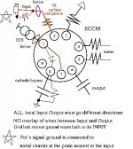
Ciao, airegin I found a little drawing/note that I use to remind myself
what to do with my CCS loaded ECC88. ECC88 Gm is 12 S, so it is not too far from your EC86.
Hope it may help.
I am interested to know the resistance of grid leak resistor that you are using ?
what to do with my CCS loaded ECC88. ECC88 Gm is 12 S, so it is not too far from your EC86.
Hope it may help.
I am interested to know the resistance of grid leak resistor that you are using ?
Attachments

This means oscillation, and it is confirmed by the radio test. (8V from leakage would prevent the valve from working at all in your circuit). The meter readings will be totally confused by the high frequency oscillations.-6.7v on left ch and -8v on right ch...
There are many things that can be done to reduce the risk of oscillation. It is worth doing as many as you can, even if the oscillation stops. All of them will improve the safety margin - and remember that even if it is stable at idle, big signals often provoke transient oscillation.
- Reduce the value of the volume pot as low as possible. This loads-down the feedback through the a→g capacitance. If you can't do this, try adding a series-RC directly across the grid. A very small C, maybe 47-100pF C0G and 5-10kΩ might be a start;
- use screened cable for the grid wiring, and run the grid wiring far away from any part of the anode circuit. Move the input and volume control if necessary;
- use moderate values of grid stopper (say 100 to 390Ω). The stopper is not a LP filter, as many believe: it is a Q-spoiler, acting against unintended tank-circuits in the anode.
- Carefully implemented decoupling of the anode supply voltage. Run some 50mm-wide copper tape over an insulator (wood for example) to provide a ground for the supply capacitors. The ground links the EC86-cathode-LED's ground to the supply capacitors (mounted directly on the CCS module).
- Supply capacitors should include: 47µF «normal-ESR» electrolytic: Panasonic M or Nichicon VR (the ESR acts as damping for low-frequency oscillation); 100-470nF Stacked-Construction MKP or MKT (these shorten the path for oscillation 1-10MHz); and if possible, a true RF decoupler: 500V C0G ceramic chip capacitors 470pF and any larger values available.
- the CCS module should be built/rebuilt to be as small as possible. I built my depletion-FET CCSs on some carved-out plain FR-4 ca. 7mm x 35mm.
- Grounded copper tape under the CCS module. And consider screening the whole CCS;
- Anode wire should be straight and short, and be far from any wiring of the cathode, grid, or heater;
- Anode stopper: I usually use 100-470R 2W wirewound resistors. The 100-700nH of inductance in the wirewound is deliberate. Lumped inductance (components) is not the same as distributed inductance of wiring. Some lumped inductance deters the highest frequencies, but does not provoke oscillation because the Q of the component is diminished by the 100-470Ω real part of the impedance. Ferrite beads also work very well, especially at higher anode current, or if the oscillation is stubborn!. Be careful to only use EMC beads (highly resistive at high frequency).
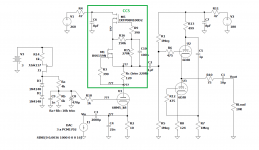
I use in my DAC 6HM5 and before 6S4P which are very similar to EC86. I have also been using CCS for a long time, before depletion + jfet and now two depletion in cascade with bias multiplier and I have no problems with self-oscillations, everything is done on PCB with ground plane.
For the upper mosfet I used DN2540 before and now IXTP08N100D2 which is a bit better.
Maybe the problem is in the 10M35S itself but I have never used them for CCS.
For the upper mosfet I used DN2540 before and now IXTP08N100D2 which is a bit better.
Maybe the problem is in the 10M35S itself but I have never used them for CCS.
Attachments
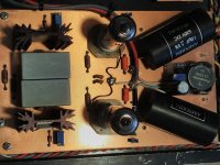
The ground plane and tightly assembled parts will really help. Nice build. The grid is looking out at 1kΩ, too - that will help a lot.everything is done on PCB with ground plane.
I have one comment after reading one page mostly so I apologise if I repeat.
Even at 6mA, a to220 case needs a good heatsink and time to warm up to stability in CCS.
A cascode of 2 devices is far more stable.
Even at 6mA, a to220 case needs a good heatsink and time to warm up to stability in CCS.
A cascode of 2 devices is far more stable.
hi,
following your advice I reduced the grid resistor to 180R, added a 100k leak resistor to lower the value of the potentiometer, put a couple of ferrites on the inputs and rationalized the wiring. the oscillation phenomena have now practically disappeared. I am quite satisfied with the final result even if the gain is still excessive in my audio chain. for the next few months I will listen to it in this configuration, then maybe I will investigate for a driver stage with gain around 30-35x ....
thanks to all!!!!
A rapid way to get lower gain:
- Replace the LED with ordinary diode, example: 1N4001;
- Add a small resistor in series: 62 .. 100Ω;
- Don't bypass the resistor.
- makes it easier to try increasing the anode current, too.
- it also reduces the effective gm, so oscillation is less likely.
How does that reduce gain? With constant current there should be no degeneration by the cathode resistor. Unless I'm missing something.....
the circuit in post #1 is a common-cathode stage. The current is only constant at idle - when a positive signal is applied (at the grid), the current increases, increasing the voltage across the cathode resistor - and acting as degenerative feedback.With constant current there should be no degeneration by the cathode resistor.
OK, so it will depend on the load of the following stage. For low loading (e.g direct coupled or into a 470k or 1M resistor) the cathode current will hardly vary from the 7 mA idle current even for high voltage swings, as the current through the load is small compared to the idle current. So degeneration effect and hence reduction in gain will be very small . For higher loading such that the load current is a significant fraction of the idle current the reduction in gain will start to become significant.
We do not need to consider large voltage swings to calculate the gain, or the degeneration.
The unbypassed resistor directly reduces gm (and thus gain) at any level of load current.
The effect can easily be evaluated without guesswork, but rather, numerically.
That's because the gm of the ec86 is a known quantity - 14mA/V at the data sheet operating point. So (using this example) the intrinsic rk is 1/gm; 71.4 ohm.
Let's say the unbypassed resistance is 75 ohm. Now the effective {small signal) gm degenerates all the way from 14 to 6.8 mA/V.
I would not call that a small effect.
gm only directly affects gain for a cascode. Gain with CCS (which is what we're talking about) is approximately equal to mu.
Yes, you're right. My mind was in cascode-mode for EC86, which works so well. Apologies for confusing anyone.Gain with CCS
- Home
- Amplifiers
- Tubes / Valves
- 10M35S CCS help