buongiorno,
this is my first attempt to use a ccs. it is for the driver section (EC86) of a single ended power amp with the 45.
I am unable to obtain a stable operating point as it vary with the variation of the volume control...
strange thing is that the power amp sounds anyway, even with 12v plate voltage ...
what could be wrong ?
grazie!
this is my first attempt to use a ccs. it is for the driver section (EC86) of a single ended power amp with the 45.
I am unable to obtain a stable operating point as it vary with the variation of the volume control...
- volume control from zero to the first quarter: operating conditions are those highlighted in RED (8mA 1.8V 12V)
- in the transition from the red to the green zone the amplifier emits a bump in the speakers
- volume control in the central part of regulation: the values suddenly change to those highlighted in GREEN (6.3mA 1.1V and at the anode vary from 40v up to 80v and then down to 40V)
- in the transition from the green to the blue zone the amplifier emits another bump in the speakers
- volume control in the last quarter to full: the values return almost the same (highlighted in BLUE) to those of the first quarter of regulation.
strange thing is that the power amp sounds anyway, even with 12v plate voltage ...
what could be wrong ?
grazie!
Attachments
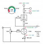
The CCS and the LED.what could be wrong ?
The tube requires stable bias point: in this case constant current, and -mostly- constant bias voltage (generated by the LED).
If the current not constant, the CCS practically not working.
Try to check CCS at -least- 30V and 40..50V with 100R load to ground (instead of tube).
If the current is stable at variable B+, CCS is working properly.
Why you choose this type of LED?
It's working as source of switched bias voltage: sometimes 1.8V, sometimes 1.1V. Nonsense.
p.s. I usually use grid leak resistor (few hundred kOhm) even if I use potentiometer.
EC86 Gm is 13S, with the CCS it might be oscillating !
Probe output of EC86 with an oscilloscope to confirm.
Use carbon grid stopper, watch for any local feedback due to "accidental" coupling (wires too close).
Probe output of EC86 with an oscilloscope to confirm.
Use carbon grid stopper, watch for any local feedback due to "accidental" coupling (wires too close).
- i changed type/brand of red leds
- added a grid leak resistor
- tried with or without the 680R grid stopper (riken carbon comp)
- completely rebuilt the CCS with two new chips, optimizing the wiring (1k resistor directly on the chip pin,...)
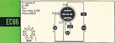
- EC86 socket have the unused clips removed (#2, #8 and #9), i used only #1 for anode, #6 for grid and #3 + #7 connected together for cathode (as suggested by Rod Coleman)
unfortunately nothing has changed
replacing the CCS with a 15K resistor the amplifier works flawless.
Attachments
If the LED voltage is varying from 1.1V to 1.8V for a current-increase of 6mA to 8mA, something is not right - probably oscillation while the volume pot is in the centre-position. At the higher volume setting, the input source is probably loading the grid.
Oscillation is very possible when the grid is fed from too-high impedance: the (unintended) feedback from the anode circuit to the grid is not suppressed by grid-loading.
You could try lower impedance across the grid, and multi-turn ferrite beads in the anode (or a 220Ω wirewound resistor) - but I think you will have trouble with the EC86 in such a circuit. It's simply because the EC86 has very high gm, and very wide bandwidth. It was designed for low-impedance anode loads, via cascode. With cascodes, the anode is essentially static, and oscillatory feedback to the grid is not so likely. OTOH, CCS loads have very high impedance, and the physical metal of the CCS circuit presents a high risk of HF/VHF coupling to other parts of the circuit.
The high-µ of the circuit with a CCS anode load will also cause DC stability problems, since depletion-FET type CCSs exhibit drift in the current as the FET self-heats to higher temperatures. It could be improved by using a cathode resistor instead of a LED; maybe not what you are aiming for, but trying it may help debug the circuit....

BTW, oscillations of this kind are easily detected with a portable radio. Tune to a very weak station in the AM region. Power up, and hold the radio near the tube, and move it, all the time adjusting the volume control. Oscillating circuit will generate all kinds of strange noises in the radio.
EC86 makes good UHF oscillator. Probably going off in the VHF range maybe even up to 400MHz. Suggest you swap it for something more audio.
Swapping the EC86 for a “more audio“ tube is a good suggestion in diagnosing the underlying problem.
However, despite the realistic objections, it would be very nice to see the EC86 made to work properly with the CCS. Question to OP - how are you physically connecting to the control grid? Are you using all three of the pins together (2, 5 & 8) with grid stopper, or just one.
However, despite the realistic objections, it would be very nice to see the EC86 made to work properly with the CCS. Question to OP - how are you physically connecting to the control grid? Are you using all three of the pins together (2, 5 & 8) with grid stopper, or just one.
8mA Ip @ 10.2 Vdc Vp is deep into the positive grid voltage potion of the EC86 plate curves. Are you sure the plate voltage is correct?operating conditions are those highlighted in RED (8mA 1.8V 12V)
as suggested by Rod i am only using one grid pin, the #6, while the #2 and #8 pins are not connected and i removed their clips from the socket.Question to OP - how are you physically connecting to the control grid? Are you using all three of the pins together (2, 5 & 8) with grid stopper, or just one.
next test I'm going to do, as soon as I get home... (250R with 50/100uF bypass cap)It could be improved by using a cathode resistor instead of a LED; maybe not what you are aiming for, but trying it may help debug the circuit....
yes, I admit that it may seem absurd also because, as I wrote, the amplifier sounds decent even under these conditions ...8mA Ip @ 10.2 Vdc Vp is deep into the positive grid voltage potion of the EC86 plate curves. Are you sure the plate voltage is correct?
I took a cue from a Palustris 2a3 amplifier, which use the EC86 (CCS loaded, LED biased) and since I had some Telefunken and Valvo I just wanted to try.EC86 makes good UHF oscillator. Probably going off in the VHF range maybe even up to 400MHz. Suggest you swap it for something more audio.
if it turns out to be too complicated I can swap the ec86 for "something more audio", as i have some c3m and some ec8010 available.
Have a read:
https://www.diyaudio.com/community/threads/need-help-with-ec86.351830/
I would suggest a 10k resistor between the CCS and the anode. Who knows.
https://www.diyaudio.com/community/threads/need-help-with-ec86.351830/
I would suggest a 10k resistor between the CCS and the anode. Who knows.
EC86 is worth sticking with. Try 1K carbon comp on one or two grids, i vaguely recall a friend of mine commenting you need two stoppers for some inexplicable reason. He only tried the tube resistor loaded though.
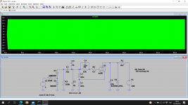
Operating points where: Red Led cathode bias, and 10K 7W WW anode load, with 300V regulated B+
Cheers,
V4LVE
Operating points where: Red Led cathode bias, and 10K 7W WW anode load, with 300V regulated B+
Cheers,
V4LVE
Have a read:
https://www.diyaudio.com/community/threads/need-help-with-ec86.351830/
I would suggest a 10k resistor between the CCS and the anode. Who knows.
A 10k resistor (or 4.7k, or somewhere in there) will take some heat off the MOSFET, which could be a good thing.
Also, perhaps try replacing the red LED with a 240R cathode resistor, as a test to see if the LED has anything to do with the problem. (240R*0.007A = 1.68V)
I have used the valve as a VHF culprits oscillator and oddly enough it would go off at UHF. The solution was a 4R7 carbon resistor to the grid and right on the pin. If I used 33R the oscillator would not run. In the end I went for an ECC86.
Attachments
Last edited:
I think I would try a couple of 4p7 ceramic from grid to cathode as short as possible on pin on both sides.
i replaced the red led with a 240r resistor and slightly raised the B+, unfortunately nothing has changed. now i have these values:
pot 0%: 247 B+, 212V plate, 2V cathode, 8,3mA
pot 50%: 269 B+, 179V plate, 1,75V cathode, 7,1mA
pot 100%: 248 B+, 210V plate, 2V cathode, 8,3mA
then I tried again to completely remove the CCS and put a 15K resistor on the plate and all the problems disappeared...
well, it would be easy for me to leave everything like that, even without the CCS I have plenty of gain to drive the 45.
but ....I need to listen it more carefully, but I seem to prefer the sound with CCS...
- Home
- Amplifiers
- Tubes / Valves
- 10M35S CCS help