Recently I have a idea of PNP transistor "direct couple" 300B grid.
PNP hfe is around 100 so it may be a candidate of 300B's single stage driver.
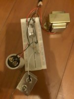
I build my circuit on bread board and do some measurement of sine ware 20Hz ~ 20KHz.
I choose 24931 PNP transistor which has max Vce 250V.
PNP hfe is around 100 so it may be a candidate of 300B's single stage driver.
I build my circuit on bread board and do some measurement of sine ware 20Hz ~ 20KHz.
I choose 24931 PNP transistor which has max Vce 250V.
Attachments
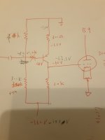
Av = 60 by measurement.
The drawback of this circuit is lower input impedance due to 4Kohm bias resistance.
If CD player or preamp has capacitance coupled output, the input capacitance can be omitted.
The drawback of this circuit is lower input impedance due to 4Kohm bias resistance.
If CD player or preamp has capacitance coupled output, the input capacitance can be omitted.
That's a brilliant little circuit! Getting 'fun' back into diy. Well done. Using a BJT with just some local feedback to drive the queen of triodes.
There will be a slight bias drift with temp, but not enough for any worries.
So how does it sound?
At low levels I'm sure the BJT is quite linear, but approaching max level? Do you have FFT measurements?
There will be a slight bias drift with temp, but not enough for any worries.
So how does it sound?
At low levels I'm sure the BJT is quite linear, but approaching max level? Do you have FFT measurements?
I appreciate your words.That's a brilliant little circuit! Getting 'fun' back into diy. Well done. Using a BJT with just some local feedback to drive the queen of triodes.
There will be a slight bias drift with temp, but not enough for any worries.
So how does it sound?
At low levels I'm sure the BJT is quite linear, but approaching max level? Do you have FFT measurements?
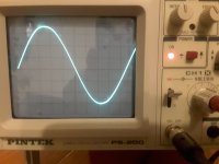
By now I only do simple measurement with 2V p-p sine wave input and output waveform is the third image in my post.
I haven't heard its sound yet.
I will try to replace the drive stage by this PNP transistor circuit in my diy 300B amp.
I will also try to do FFT measurement when I have the chance to use digital oscilloscope.
Regards.
My principle is great sound by simple circuit topology.
It is not easy to create sound character with complex circuit.
Just beyond the circuit analysis.
My idol is Prof. Razavi
It is not easy to create sound character with complex circuit.
Just beyond the circuit analysis.
My idol is Prof. Razavi
Probably this one: 2N4931Any more details on the transistor? Googling that number just brings me to this thread.
https://eu.mouser.com/ProductDetail/Microchip-Technology/2N4931?qs=TXMzd3F6EymwpgDD/tdo4Q==
You can do FFT with a much cheaper setup, a decent sound card, supported by REW software, which is free.I appreciate your words.
By now I only do simple measurement with 2V p-p sine wave input and output waveform is the third image in my post.
I haven't heard its sound yet.
I will try to replace the drive stage by this PNP transistor circuit in my diy 300B amp.
I will also try to do FFT measurement when I have the chance to use digital oscilloscope.
Regards.
I mistype the number : PNP 2N4931Any more details on the transistor? Googling that number just brings me to this thread.
Thank you for your correction!
Yes 2N4931
I would suggest Motorola NOS transistor :
https://www.ebay.com/itm/324973598741?hash=item4ba9ef9815:g:eR0AAOSwvhJh0lT8
Thank you for your suggestion!You can do FFT with a much cheaper setup, a decent sound card, supported by REW software, which is free.
I will try it.
If you are going to RC couple the input, then you could do it with a NPN, a N-JFET, P-JFET etc. You could (folded) cascode a couple PNP's directly off the driver tube plate, ie no capacitor, as long as you have enough combined Vceo to reach from ~+200 down to -100. But then a fading driver tube would shift the 300B bias, not good. You also could regulate the 300B DC current with more transistors. Do you have a design objective that decides how much silicon you use, vs tubes? The popular MJE350 can handle 300V and the power that comes with high voltage drops. Have fun with this.

Thank you for your words.If you are going to RC couple the input, then you could do it with a NPN, a N-JFET, P-JFET etc. You could (folded) cascode a couple PNP's directly off the driver tube plate, ie no capacitor, as long as you have enough combined Vceo to reach from ~+200 down to -100. But then a fading driver tube would shift the 300B bias, not good. You also could regulate the 300B DC current with more transistors. Do you have a design objective that decides how much silicon you use, vs tubes? The popular MJE350 can handle 300V and the power that comes with high voltage drops. Have fun with this.
There is no complementary type in tube world so I think about using PNP transistor (or PMOS, P-JFET) to direct couple 300B.
When PNP transistor fails or fades, 300B bias shift to more negative. So it is safe.
Cascode is also an option. We have to worry the situation when the CG FET/MOS fails.
Any circuit-bender should be able to count THDs on thumbs.linear, but approaching max level?
Well-used tube and FETs run 5% at 90% of clipping. BJTs can run closer to 26%.
However there is a 300r emitter resistor on a BJT run at Hie about 6 Ohms. That's 50:1 of NFB so THD may be 0.5%.
The 300B may be 5%-10% THD but opposite phase. So we estimate 4.5%-9.5% THD. The transistor distortion is nearly negligible. Not quite because distortion cancellation is never perfect. But no tube is as clean as this. Or as cheap.
Transistor distortion will be very low as he has 5ma bias and 160v of supply.
Tube distortion will dominate.
I am using ksc1845 for concertina with .003 % or less distortion at 10v p - p both sides
Tube distortion will dominate.
I am using ksc1845 for concertina with .003 % or less distortion at 10v p - p both sides
When PNP transistor fails by Ec short (as they sometimes do) your 300B current will skyrocket and you can kiss it goodby!When PNP transistor fails or fades, 300B bias shift to more negative. So it is safe.
I never subject any of my valuable output tubes to that risk!
Fuse the cathode?
Or at least monitor the voltage on a 1 ohm resistor in the cathode, and shut down the power on overload.
Or at least monitor the voltage on a 1 ohm resistor in the cathode, and shut down the power on overload.
We should be able to address this by turning the circuit upside-down, and replacing the PNP with an NPN transistor. The NPN will then be below the grid. Now, a short-circuit failure should pull the grid negative, and if there is also a low-value fuse in the collector circuit, it should stay there.When PNP transistor fails by Ec short (as they sometimes do) your 300B current will skyrocket and you can kiss it goodby!
Changing to an NPN will improve performance, too, especially for high voltage parts. Try the KSC3503, with its very low Cob, 300V durability, flat Hfe, and useful SOA.
But if it fails open you’re back to the same problem. Perhaps worse because the magnitude of the tail voltage is higher. Six of one, half dozen of the other. Second breakdown is highly unlikely with any of these parts given the collector resistor value. The load just isn‘t very heavy. But a base-emitter short from input overload could potentially occur, but you’d have to drive it stupid hard with a lot of distortion for an extended period to do it. People who listen to 300B’s don’t do that. They tend to like the music to sound good.
But the KSC3503 is an excellent choice of device - and probably better than it’s PNP equivalent.
But the KSC3503 is an excellent choice of device - and probably better than it’s PNP equivalent.
Open failures, like bond-wire vaporising on account of gross overcurrent seem highly unlikely in this circuit.Six of one, half dozen of the other.
But yes: at 60V, 3mA shorts are also probably rare.
Still, the PNP version has other vulnerabilities: for example, power switch-ON and switch-OFF events may cause overvoltage transients, and these might give rise to excess base-collector leakage current. That could easily send the grid positive with a PNP, but would be safe with NPN.
Another protection device is recommended, since we're talking about reliability: A small diode antiparallel to the B-E junction (in all cases), to protect the junction from reverse voltage transients, which are likely enough giving the coupling cap.
- Home
- Amplifiers
- Tubes / Valves
- PNP Bipolar Transistor Single Stage "Direct Couple" 300B