Hello to you all, I've been looking round the net for Class D help and this forum looks like the right place.
I've been repairing pro-audio amps on and off for years now but have only recently started seeing more Class D, I 've repaired a few with simple problems and a couple of small chip amps but I've decided now to learn as much as possible about Class D and associated SMPS. I have a non functional Peavey IPR 1600 as a study subject. I'll attach the schematic and a couple of scope traces.
Ok when the amp arrived it had blown the two side B output mosfets (IRF4227) , the IRS2092 (same side) was shorted (not sure about the other at the moment) in the amp and in the SMPS which uses: Q5 (MTP2P50), IC13 (LR654N), IC17 (LM317P), IC14 (555), Q8 (PNP), IC15 (UC3525), IC11 (IR2110) ... the IR2110 was shorted as were the 18v zeners and 5819 schottky diodes on both of the IGBT gates. I expected the IGBT's (STGF19NC60KD) to be shorted too but after close scrutiny they seem to still be functioning properly. Parts arrived and as with all other classes I started on the power supply.
I replaced the IR2110 & both sets of gate zeners and 5819's, then scoped the HO & LO outputs, it was at this point that I realised how unfamiliar I am with these amps.
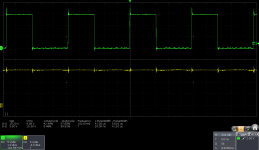
The LO is showing a switched output but the HO just seems to be DC and there is no switching at the transformer and so no voltage on secondary side.
I've been reading the last couple of days so I see that the HO switching is controlled by the boostrap circuit on VS & VB so I removed all components from this circuit and all test fine so I'm just confused now as to how to troubleshoot the lack of switching on HO. I'm unclear as to whether this is a fault or if it's because of something I have done/not done yet?
Here are IR2110 pin voltages:
VSS = 0v
SD = low
VDD/VCC = 16v
VB = 15.6v
VS = 15v
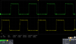
LIN, HIN, LO, HO are detailed on the scope traces.
If any of you can help me understand how this works properly it would be well appreciated ... attached are the 3525 output traces (so IR2110 inputs) & IR2110 output traces with no switching on HO.
I've been repairing pro-audio amps on and off for years now but have only recently started seeing more Class D, I 've repaired a few with simple problems and a couple of small chip amps but I've decided now to learn as much as possible about Class D and associated SMPS. I have a non functional Peavey IPR 1600 as a study subject. I'll attach the schematic and a couple of scope traces.
Ok when the amp arrived it had blown the two side B output mosfets (IRF4227) , the IRS2092 (same side) was shorted (not sure about the other at the moment) in the amp and in the SMPS which uses: Q5 (MTP2P50), IC13 (LR654N), IC17 (LM317P), IC14 (555), Q8 (PNP), IC15 (UC3525), IC11 (IR2110) ... the IR2110 was shorted as were the 18v zeners and 5819 schottky diodes on both of the IGBT gates. I expected the IGBT's (STGF19NC60KD) to be shorted too but after close scrutiny they seem to still be functioning properly. Parts arrived and as with all other classes I started on the power supply.
I replaced the IR2110 & both sets of gate zeners and 5819's, then scoped the HO & LO outputs, it was at this point that I realised how unfamiliar I am with these amps.
The LO is showing a switched output but the HO just seems to be DC and there is no switching at the transformer and so no voltage on secondary side.
I've been reading the last couple of days so I see that the HO switching is controlled by the boostrap circuit on VS & VB so I removed all components from this circuit and all test fine so I'm just confused now as to how to troubleshoot the lack of switching on HO. I'm unclear as to whether this is a fault or if it's because of something I have done/not done yet?
Here are IR2110 pin voltages:
VSS = 0v
SD = low
VDD/VCC = 16v
VB = 15.6v
VS = 15v
LIN, HIN, LO, HO are detailed on the scope traces.
If any of you can help me understand how this works properly it would be well appreciated ... attached are the 3525 output traces (so IR2110 inputs) & IR2110 output traces with no switching on HO.
Attachments
Last edited:
How come the voltage at VB w.r.t. VS is only 15.6 - 15 = 0.6V, that way the high-side driver does not get the bootstrapped power supply ? The voltage VB-VS, for a working half-bridge should measure within a diode drop of VCC-COM i.e. (15V in your case), don't you think ?
And, are you showing HO w.r.t VS and LO w.r.t COM?
And, are you showing HO w.r.t VS and LO w.r.t COM?
It's still OK, you may not need to repeat any measurements, as both VB and VS are w.r.t. COM, their difference is going to be the same any way.
Also, since the max duty for half-bridge is about 50%, the low-side must and will switch regularly thereby charging the bootstrap capacitor. I would check the low-side IGBT for an open-circuit failure. Once the low-side switching is restored, the high-side driver would then get its power supply properly and come out of UVLO, hopefully bringing back some switching action.
In short, you need to read 15V (put a multimeter across the bootstrap capacitor), before the circuit works properly. Don't use your oscilloscope, as VS is a switching node.
Last edited:
HO wrt VS on the scope looks a lot better, but still no secondary voltage, thanks for the advice I'll get more time later to investigate further ... 🙂

Well, in that case you should now have a zero-average output voltage across the transformer primary winding (VS wrt centre tap VDC/2).
BTW, do you have a differential oscilloscope ? If you don't then you just shorted VS and COM together !! The HO may start working (due to the bootstrap cap charging through the short) but there's going to be a ground current through the oscilloscope. I hope your scope is differential.
BTW, do you have a differential oscilloscope ? If you don't then you just shorted VS and COM together !! The HO may start working (due to the bootstrap cap charging through the short) but there's going to be a ground current through the oscilloscope. I hope your scope is differential.
Last edited:
No I don't have a diff scope. Can you explain (VS wrt centre tap VDC/2), not sure what you mean.
Sorry if it's taking ages for me to reply, all my posts have to be checked by moderator still ...
Sorry if it's taking ages for me to reply, all my posts have to be checked by moderator still ...
Amp is connected through an isolation transformer, yes I think the bootstrap cap is only charging through the short. So looks like a fault with low side IGBT. I've had the IGBT's out twice already and both times it tested fine with multimeter and microprocessor transistor tester ....If you don't then you just shorted VS and COM together !! The HO may start working (due to the bootstrap cap charging through the short) but there's going to be a ground current through the oscilloscope. I hope your scope is differential.
Last edited:
Damn it just realised what you meant ... I'm not paying attention. Ok won't do that again ... no harm done hopefully. I'll be a lot more careful from now on, this is the 1st time I'm dealing with these switching IC's, please point out any further potential pitfalls ...
Is the logic signals into the 2110 ok? Probably. If you lift the gate resistors and schottky diodes then short the output to GND, the high side will be reff'd to GND and get bias thru D10. Now both outputs should just switch reff'd to GND and it should be easier to probe...
Have you checked the gate resistors? They tend to go high-ohmic after an output device fail.
Edit: You may want to disconnct the power device's voltage rail, or at least pull the IGBT's gates low while doing this test.

Have you checked the gate resistors? They tend to go high-ohmic after an output device fail.
Edit: You may want to disconnct the power device's voltage rail, or at least pull the IGBT's gates low while doing this test.
Yes checked gate resistors they were fine ... I'm pretty sure it's it's open circuit Low side IGBT but I want to learn as much as possible from this so will do what you suggest tomorrow.
Also can't seem to find the STGB19NC60KDT4 IGBT's needed here available anywhere, does anybody have a suggestion for equivalent replacements?
Can you explain that part in more detail please?Edit: You may want to disconnct the power device's voltage rail.
Also can't seem to find the STGB19NC60KDT4 IGBT's needed here available anywhere, does anybody have a suggestion for equivalent replacements?
Last edited:
Is the logic signals into the 2110 ok?
Do you mean LIN & HIN? if so,
No I don't have a diff scope. Can you explain (VS wrt centre tap VDC/2), not sure what you mean.
Well, that's a measurement across the primary winding of the transformer, but since that's a floating measurement (and you're not differential), it no longer applies, so don't bother to try.
What about pseudo differential measurements?
I guess, you mean two-channel (A-B) measurement by "pseudo-differential". That's OK as long as the common-mode rejection is good. However, that depends on the channel-channel matching of the oscilloscope in question.
You need to remove the 330V mains power before shorting VS and COM.Can you explain that part in more detail please? Also can't seem to find the STGB19NC60KDT4 IGBT's needed here available anywhere, does anybody have a suggestion for equivalent replacements?
If cost is no issue, then you may replace the IGBTs with MOSFETs (with same gate-drive circuitry) for better reliability. Easily available direct replacements could be:
IRFP460N - 500V, 20A.
SPW47N60C3 - 650V, 50A.
However, these are not TO-220, and you may also need to adjust the gate resistor accordingly.
Not sure anything works if removing the 330V, so rethinking you will only need to short gates to emitter just to ensure the device does not turn itself on.
Or use a bench supply for the SMPS circuitry running with the IR2110.
I don't think you need monster MOSFETs here. The IGBTs are good for 20A. This is the high voltage input driving the primary, and the current is much lower than on the secondary side. Bigger devices just means more switching losses, besides not sure the IR2110 can drive them properly. I would search for MOSFET rated to about 20A, with a Vds of 600V or more. The lower gate charge the better, and as long as Vds and Idd is similar, chose the one with lowest Qgtotal.
However, these are not TO-220......
IRFB18N50 & IRFB20N50 appear to be suitable alternatives in the TO-220 package.
Besides, let me say, once again, that VS being the output pole of the half-bridge and COM being its return would require any method that involves shorting these together to have the mains power to be turned off in the first place.
the supply is a resonant dcdc converter, resonating L9 and C77,C79. you can observe sinusoidals on the aux winding. operating freq is usually a bit above the resonance freq.
If cost is no issue, then you may replace the IGBTs with MOSFETs (with same gate-drive circuitry) for better reliability. Easily available direct replacements could be:
IRFP460N - 500V, 20A.
SPW47N60C3 - 650V, 50A.
However, these are not TO-220, and you may also need to adjust the gate resistor accordingly.
Thanks guys this info is very valuable to me ... better reliability is always of great interest for pro-audio gear, I've got no previous experience of IGBT in amps, so you say mosfets would give better reliability. The IGBT's btw are not TO-220 ... they are D2PAK.
I'm in Scotland and at the moment there's a complete drought of components in the UK especially anything D2PAK & ordering abroad is very expensive for shipping. I was starting to consider buying TO-220 and trimming them to D2PAK shape.
I'll need to look into gate resistor adjustment.
Not sure anything works if removing the 330V, so rethinking you will only need to short gates to emitter just to ensure the device does not turn itself on.
Or use a bench supply for the SMPS circuitry running with the IR2110.
I don't think you need monster MOSFETs here. The IGBTs are good for 20A. This is the high voltage input driving the primary, and the current is much lower than on the secondary side. Bigger devices just means more switching losses, besides not sure the IR2110 can drive them properly. I would search for MOSFET rated to about 20A, with a Vds of 600V or more. The lower gate charge the better, and as long as Vds and Idd is similar, chose the one with lowest Qgtotal.
Thanks for that info on characteristics, I've got an RS warehouse about 20 miles away and up to a couple of years ago I could get literally any parts required next working day delivery. Now though I find I'm constantly trying to find equivalents from what's available because lead times on popular components here are well into next year. Mouser are most reliable here but that adds £12 to the price for shipping & I can't always justify spending enough for free delivery.
IRFB18N50 & IRFB20N50 appear to be suitable alternatives in the TO-220 package.
Besides, let me say, once again, that VS being the output pole of the half-bridge and COM being its return would require any method that involves shorting these together to have the mains power to be turned off in the first place.
Thanks for the component suggestions I'll look into that ... I've got a 3A 15v dual supply here somewhere that I'll use if I can dig it out.
the supply is a resonant dcdc converter, resonating L9 and C77,C79. you can observe sinusoidals on the aux winding. operating freq is usually a bit above the resonance freq.
That sounds interesting, can you detail how it is done?
Thanks for all the replies, a lot to look into ... I've been roped into some stuff with the family today but if I get time later I'll see if I can find my old dual supply and see what I can do. That's interesting that mosfets are considered more reliable, I'll have a dig about and see what I've got here.
- Home
- Amplifiers
- Class D
- Class D repair help please, 3525, IR2110, IGBT