Basics 🙂
Add up all the base/emitter volt drops you have to overcome in order to bias the output and driver stage. You need at least that voltage across C421.
Add up all the base/emitter volt drops you have to overcome in order to bias the output and driver stage. You need at least that voltage across C421.
surley this is something generic though affecting both? what are the odds that the same issue is affecting both seperatly in circuit?Basics 🙂
Add up all the base/emitter volt drops you have to overcome in order to bias the output and driver stage. You need at least that voltage across C421.
Ah you just reminded me of an issue i had with one of these before
The centre voltage on these is affected by the idle, and i proved this before, and i have had trouble with that today, so you could be onto the right area
you can, on most nads alter the centre voltages so they are correct, when the idle is wrong, but this puts the position of the trimmer in the wrong possition, and i know exactly where they should be on each model, and i have had to position these differently today to get 0v.
i will report back tomorrow, but now its time for a couple of beers 🍺 some chinese 🥢
Bias current and midpoint (dc offset) voltage should really be pretty much independent of each other. See what voltage you have across C421.
OK I'll check tomorrow, but everytime I've had an idle or centre issue, once corrected I've always had to go back and readjust the other
The dc offset and bias current would normally only interact if there was a load drawing current and there was also an offset present. That is one reason why the current adjustment should be done without a load connected.
do you think it is possible to have exactly the same fault on both channels at the same time.
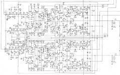
here is where i am
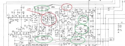
i did as suggested and the current across both of those caps is just over 3v on each
what is strange is i only have about -1.5v on Vr01
now im thinking it could be one of the zeners, but would you have the same issue exactly on both?
here is where i am
i did as suggested and the current across both of those caps is just over 3v on each
what is strange is i only have about -1.5v on Vr01
now im thinking it could be one of the zeners, but would you have the same issue exactly on both?
Attachments
ive managed to set both currents now, so is the above right, and im just an idiot?do you think it is possible to have exactly the same fault on both channels at the same time.
here is where i am
i did as suggested and the current across both of those caps is just over 3v on each
what is strange is i only have about -1.5v on Vr01
now im thinking it could be one of the zeners, but would you have the same issue exactly on both?
i think i just had one of those der.... moments😱
Last edited:
The Zeners should have the correct voltage across them. If both channels are the same then the obvious common factor is the +61v supply. Next up are the 15k's feeding the Zener and then the Zener itself.
Providing the circuit hasn't been got at 😀 then there can be nothing else because the Zener connects to high impedance circuitry (the 10k preset and its 47k going to the wiper).
So it has to be one of those three things or else the amp has a man made fault.
Providing the circuit hasn't been got at 😀 then there can be nothing else because the Zener connects to high impedance circuitry (the 10k preset and its 47k going to the wiper).
So it has to be one of those three things or else the amp has a man made fault.
The amp works ok, so are the voltages(both are the same) incorrect at -1.5v on the trimmerThe Zeners should have the correct voltage across them. If both channels are the same then the obvious common factor is the +61v supply. Next up are the 15k's feeding the Zener and then the Zener itself.
Providing the circuit hasn't been got at 😀 then there can be nothing else because the Zener connects to high impedance circuitry (the 10k preset and its 47k going to the wiper).
So it has to be one of those three things or else the amp has a man made fault.
voltages at the zeners are correct +4v and -4v
both are correct 0v to ground, so iwas trying to find a fault that wasnt there.
told you i had a duff brain sometimes 😉
Last edited:
-1.5v is OK on the wiper of the trimmer as that is the voltage needed to achieve zero volts offset at the output. The wiper should swing between the two Zener voltages, so between - and + 4.7 volts.
So is it all OK in the end?
So is it all OK in the end?
yes all ok, in fact the only thing that threw me to start with was there was a dry joint on Q411 and i was getting a high voltage on the trimmer, so other than that there was nothing wrong aprt from 2 new 1k trimmers on the idle.
It must have been that rum i had last night 😉 as when i felt the heatsink it was warm so there had to be current, it was just i hadnt set the trimmers round far enough to start getting current.
what a donut 🤣
It must have been that rum i had last night 😉 as when i felt the heatsink it was warm so there had to be current, it was just i hadnt set the trimmers round far enough to start getting current.
what a donut 🤣
mmm on both counts i recon, anyway onwards to the next couple today👉............ another arcam 5 and a cambridge audio A1 mk3
- Home
- Amplifiers
- Solid State
- NAD 3240PE-No idle either channel