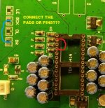
Connections look correct.
For TDA1541A and I2S input, DR is left open. If your chip is a non-A TDA1541, then DR (pin 4) needs to be connected to pin 2.
For I2S input, the I2S mode needs to be selected. On the D3 that is done on the underside of the board:
hello Ben Mah,
thanks for the info, yes i've connected the jumper into i2s mode.
the chip is tda1541 non A, so i should connect the Data/R pin4 with BCK pin2,
connect from the pads or the chip pins?
thanks.
Peter
Attachments
Your choice.
Safest would be to do it at the underside of the board. It would need to be undone if you use an A chip.
A bit riskier would be to do it on the chip pins, above the socket. But it is feasible if you have a steady hand and small tip on your iron. Advantage is no need to undo the connection on the bottom of the board if you use an A chip.
Correction: Pin 2 to 4 connection may be left in place if A chip is used in I2S. Pin 2 to 4 connection needs to be removed if simultaneous mode is used.
i mean the question is about, the connection should be done before the attenuator or after,Your choice.
Safest would be to do it at the underside of the board. It would need to be undone if you use an A chip.
A bit riskier would be to do it on the chip pins, above the socket. But it is feasible if you have a steady hand and small tip on your iron. Advantage is no need to undo the connection on the bottom of the board if you use an A chip.
but i think its before the attenuator, so connect pin2&4 directly from the chip pins. (not from the pads / ufl connector)
so with A or non A, pin 2&4 connected when in i2s mode.Correction: Pin 2 to 4 connection may be left in place if A chip is used in I2S. Pin 2 to 4 connection needs to be removed if simultaneous mode is used.
ok understood.
thanks.
Peter
The pin 2 to 4 connection is at the chip. It can be done directly on the chip or at the underside of the board at the chip pins.
ok great, thanks.The pin 2 to 4 connection is at the chip. It can be done directly on the chip or at the underside of the board at the chip pins.
btw, anyone knows how to run this NOS dac i2s into "slave" mode?
because my source of wireless streaming device have the i2s out in "master" mode.
because my source of wireless streaming device have the i2s out in "master" mode.

ok👍The D3 board is "slave" as it does not have its own clock.
thanks BenMah
hello, what capacitors would it be appropriate to use at positions C19 and C22 I don't have a black gate? I have little dynamics. The boards worked on the first circuit.🙂🙂
Hi,hello, what capacitors would it be appropriate to use at positions C19 and C22 I don't have a black gate? I have little dynamics. The boards worked on the first circuit.🙂🙂
I use Elna cerafine and silmic in these positions. I like them more than the oscon.
If your problem is too little dynamics than maybe your IV resistor value is too low. If they are too low you will lose dynamics. In most cases 34ohm is optimal But you can go higher up to around 60ohm, your distortion will also increase though.
Attachments
Last edited:
Thanks for the advice. What kind of carafine do you have? Maybe I'll find one tomorrow. I like your project. 👍
Thanks for the complement. The balanced setup of the D3 design is very good sounding.
The ROA type: https://www.hificollective.co.uk/catalog/-c-61_68_325.html
silmic will also suit and the difference is not big but depending on the sound balance in your setup one or the other will give tou a tad nicer balance: silmic is a soft and very detailed, cerafine is more dynamic but can be a little more course.
Also the type of IV resistor is important for the sound. A nice tantalum resistor can sound very good and is the most dynamic sounding of them all.
Ryan,
Will there be another board run? Sorry if I missed you already answering this.
If anyone here does. It have my build D3 build guide please let me know.
Cheers,
Greg
Will there be another board run? Sorry if I missed you already answering this.
If anyone here does. It have my build D3 build guide please let me know.
Cheers,
Greg
This discussion of caps at C19, C22 prompted me to try something that was in the back of my mind for some time. I tried 'small' 1.5F supercaps on the +5v and -5v rails. In my set up in my room effect is good and fairly pronounced. It had the effect of sharpening image and removing background noise. Very much like a clock upgrade. It removes a blur in the image you did not know was present. I use old nescaps https://www.mouser.com/ProductDetai...BMOD0001-P005-B02?qs=W0yvOO0ixfEzFv8/5TnOWA==.
Full disclosure, I use a very different set up. I still use Ryan's D1, so maybe my experience fixes a problem not here in D3. The D3 equivalent would be paralleling C15 and C7. You'd also need to confirm that the D3 power supply can handle powering it as the super cap took 3 minutes to come up to voltage. If interested, try at your own risk. I may capture some before and after sound clips and post them if my phone mic is sensitive enough to show it.
Full disclosure, I use a very different set up. I still use Ryan's D1, so maybe my experience fixes a problem not here in D3. The D3 equivalent would be paralleling C15 and C7. You'd also need to confirm that the D3 power supply can handle powering it as the super cap took 3 minutes to come up to voltage. If interested, try at your own risk. I may capture some before and after sound clips and post them if my phone mic is sensitive enough to show it.
Here is a link to a video clip playing a percussion track before adding supercaps to +-5v supplies of 1541a
Now the same track after adding supercaps
Just recorded using android phone with built in mics. Not nearly the same as being there, but I think with headphones you can get a sense of the difference.
Hi: I love this song and the way that your system reproduce it.Just for reference, a short sample of a viola. In room, very transparent. See if you can hear the breath of the performer.
🙂
In your opinion can 1.5F supercaps be used in any implementation of the TDA1541A (DAC or CD player)?
Have fun!
Glad you like it. These are tracks from MA Recordings samplers.
Yes. For years I powered +-5v with my best effort linear power supplies. Lots of clc filtering... tons of BlackGate caps. Sounded great.
Just added the very rudimentary supercaps the system sounds much better. More dynamic contrast and a more natural timber. More pronounced on more typical music but can't show it as YouTube blocks copyright. There is something about supercaps on digital power supplies that brings out the best.
Only caution is a supercap will draw lots of current while it charges. Possible some existing power supplies will overheat during initial charge up. I have had no problem with 7805 regs with heat sinks. My rig uses discrete Salas shunts with heat sinks on transistors. No issues.
Last edited:
- Home
- Group Buys
- DIY TDA1541A PCB "D3"