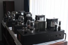
I'm fixing 4 PSE 300B amps for someone. 2 hummed badly and all had a very poor implementation of a bus earth. 2 didn't even have a proper safety earth.
All had the 25W 300B cathode resistors mounted on strips of aluminium. They were getting very hot dissipating 5W, and one was open-circuit.
I moved the cathode resistors to the chassis but measured a deterioration in noise by ~3dB on each amp. I didn't remove the powder coating under them but thermally it's way better than before.
Before:

After:

The heaters being DC I replaced the 10-turn pots with resistors. I eliminated replacing the pots as the culprit on the 4th amp when I replaced the cathode resistors and left the pots in place and measured the same deterioration. Adjusting the pots a couple of turns either side of their centre point made no difference to the noise level anyway.
I've read that transformer core flux can flow in the chassis and introduce hum into the audio ground. The top of these chassis is 10mm thick.
But could core flux in the chassis include noise in resistors screwed to the chassis?
The amps sound great on my system and you have to move very close to the speakers to hear some combination of 50Hz, 100Hz and maybe harmonics. The owner has more sensitive speakers than I do though.
All had the 25W 300B cathode resistors mounted on strips of aluminium. They were getting very hot dissipating 5W, and one was open-circuit.
I moved the cathode resistors to the chassis but measured a deterioration in noise by ~3dB on each amp. I didn't remove the powder coating under them but thermally it's way better than before.
Before:
After:
The heaters being DC I replaced the 10-turn pots with resistors. I eliminated replacing the pots as the culprit on the 4th amp when I replaced the cathode resistors and left the pots in place and measured the same deterioration. Adjusting the pots a couple of turns either side of their centre point made no difference to the noise level anyway.
I've read that transformer core flux can flow in the chassis and introduce hum into the audio ground. The top of these chassis is 10mm thick.
But could core flux in the chassis include noise in resistors screwed to the chassis?
The amps sound great on my system and you have to move very close to the speakers to hear some combination of 50Hz, 100Hz and maybe harmonics. The owner has more sensitive speakers than I do though.
Attachments
I didn't actually listen to all the amps before modifying them. I only measured them, but I'd say hum.
This is a before

and this is an after moving the resistors to the chassis:

It could just be variations in my measurement setup over time. I'll see what the guy I volunteered to fix them for thinks. They certainly sound OK to me.
This is a before
and this is an after moving the resistors to the chassis:
It could just be variations in my measurement setup over time. I'll see what the guy I volunteered to fix them for thinks. They certainly sound OK to me.
The level of the 100 Hz component stays the same, the noise floor increases, assuming the resolution bandwidth/bin size is the same (which seems to be the case, as the width of the 100 Hz peak also doesn't change). Particularly 1/f noise goes up.
I can't think of a way how moving a resistor can cause this. Replacing a resistor with a carbon composite model could cause it, but you didn't do anything like that. Weird...
I can't think of a way how moving a resistor can cause this. Replacing a resistor with a carbon composite model could cause it, but you didn't do anything like that. Weird...
Last edited:
Maybe you can try out connecting chassis directly to PE and a completely separated Audio GND with a 10 Ohm 2W to the central PE point? Also make sure the top cover has a sturdy and solid connection directly to the PE point too. Often chassis is used as a circuit conductor (wrong practice) and in many cases chassis are made from steel and then these effects can occur. The casing and its covers should be the only things connected directly to PE for safety.
Second thing I would check is if the core of the power transformer is connected to chassis or not.
Second thing I would check is if the core of the power transformer is connected to chassis or not.
Last edited:
Thanks. If the owner isn't happy there are are few other things I can do.
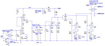
- rectify the ECC82 and 6SL7GT heaters and avoid running AC up to the small-signal end of the chassis. Currently they're AC and the wiring could be twisted a lot more and moved to the corners of the chassis away from the tubes.
- move the balanced to single-ended transformer from the noisy end of the chassis next to the input tube.
- add more filtering to the rectified 300B heaters.
Mmmm, I am not so sure if the ideas will improve the "resistors to chassis" issue. You likely have a ground(ing) issue.
- move the balanced to single-ended transformer from the noisy end of the chassis next to the input tube.
The balanced to single-ended transformer should indeed be at the input tube and far way from power transformers.
Good point. Still I would take chassis out of the audio circuit if it is like that. Something is injecting garbage into chassis and the resistors seem to pick it up.
Sorry, but these are mostly a follow-up actions.there are are few other things I can do.
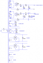
In the amp very long grounding wires (connected to star ground point) and several grounding buses, which are would generate (induced) noise/hum.
Try to shortened this.
Try to use individual -virtual- grounding points for EACH stages (each 300B is the "stage"), where tied each component "ground leg".
For example R15/R16 and C10/C13 MUST connect to own cathode resistor R12/R14 cold point, and these individually connect to ground point.
Just to be sure: are the before and after measurements done on the same amplifier with the same valves? Otherwise it could just be exemplaric spread between the amplifiers.
I'd only used star grounds before so I did some research. I found Grounding and Ground Schemes very helpful. I tried to approximate Fig 15.10b "Improved bus ground that closely approximates a multiple star ground" which is pretty much what you suggest. I say "approximate" because I didn't want to completely unwire and rewire the amps.In the amp very long grounding wires (connected to star ground point) and several grounding buses, which are would generate (induced) noise/hum.
Try to shortened this.
Try to use individual -virtual- grounding points for EACH stages (each 300B is the "stage"), where tied each component "ground leg".
For example R15/R16 and C10/C13 MUST connect to own cathode resistor R12/R14 cold point, and these individually connect to ground point.
Same amp and tubes, just with the 300B cathode resistors re-located. Now that I re-look at my dozens of measurements I'm starting to wonder if it could also be variation in conditions. The mains varies between 320VAC and 345VAC over the day here.Just to be sure: are the before and after measurements done on the same amplifier with the same valves? Otherwise it could just be exemplaric spread between the amplifiers.
100hz is ripple so that would mean ineffective filtering. Set your meter to AC and measure the 300b filaments.
The 100 Hz peak stays constant in the spectrum plot. The noise floor goes up, especially at low frequencies.
Resistors that vary randomly over time and have a DC bias (carbon composition resistors for example), interface layer between cathode tube and oxide layer, crystal defects in semiconductors. All sorts of things, but not mounting a resistor differently. I don't get it.
A rotten contact could do it, that's also a kind of randomly time-variant resistor. It would be peculiar if all four amplifiers had rotten contacts after moving the resistors, though.
I'll do that. Improving the filtering on the 300B filaments wouldn't be too difficult to do based on a suggestion in a different thread. Each 300B filament has a separate power supply with a dedicated transformer winding and a 10,000uF capacitor. Parallel the windings, replace the bridge with schottky diodes and use both 10,000uF capacitors separated by a large wattage 2Ω resistor.100hz is ripple so that would mean ineffective filtering. Set your meter to AC and measure the 300b filaments.
I've wondered that too. I really need to get an external USB sound card for my testing. It should be quieter than the current one inside the PC.What causes sloping noise floors? I’ve noticed it when doing measurements with sound cards.
- Home
- Amplifiers
- Tubes / Valves
- Deterioration in noise after screwing 25W 300B cathode resistors to chassis