Hello, I am designing a USB phone charger. I want to put this in my PSUs, so I can charge my phones and laptop.
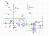
Here is the schematic.
The JD6606 is controlling output through the power FET. According to its manufacturer, it can go upto 20V. However, when I go over 6V DC in input, it stops working.
If I keep it under 6V and put my Samsung Galaxy, it says "fast" charging and consumes 7-8W (output is 5V). I want to reach 12V and 20V to be able to charge my laptop too.
I am thinking to keep Vdd 6V, despite the input on the FET. But I don't know if I have to touch feedback or anything else. Any ideas?
Attachments
Nah, it surely worth the effort.
Which charger is this that charges with 65W laptops and mobile phones and costs under $20??? Because I paid 25 EUR without shipping from China and in 6 months it was kaput.
I bought a more expensive one and was gone in 1 year.
MIne for 10 pieces from JLPCB total cost 60 bucks.
And of course this is DIY, so I want to do it myself. And put it in the LAB PSUs.
Last edited:
A looked at the data sheet and cannot stop wondering: Is this a linear regulator?Nah, it surely worth the effort.
Which charger is this that charges with 65W laptops and mobile phones and costs under $20??? Because I paid 25 EUR without shipping from China and in 6 months it was kaput.
I bought a more expensive one and was gone in 1 year.
MIne for 10 pieces from JLPCB total cost 60 bucks.
And of course this is DIY, so I want to do it myself. And put it in the LAB PSUs.
Very unlikely. Did you see all the features?A looked at the data sheet and cannot stop wondering: Is this a linear regulator?
the pdf is this:
https://datasheet.lcsc.com/lcsc/2107151900_Fitipower-Integrated-Tech-JD6606SP5_C2836123.pdf
Third world prices are different, because our wages are way lower.
I have paid 50 cents for a USB charger, and that would charge an iPhone 7, no issues. The iPhone charger broke, just out of warranty...
Laptop charger with +5-0-+18, Microsoft laptop was about $50, original.
Knock off, $20.
Used, $10.
Just do the math, then build.
Add the parts cost, and big issue is housing and wires.
I use a fair amount of LM317s.
Many times having it drive a pnp transistor like a MJ2955, can give 3-4 amps (along with a fair amount of heat). For best performance try and not have too much input voltage on it. If you want more than a half of an amp be prepared to use a decent heatsink. I use nearly the same circuit on all of them.
Have used a laptop supply on an amateur radio, with transmitter output being driven at 20v with the rest of the circuit run at 12v and the arduino supply at 5v on another 317. Pretty much what you describe.
Yeah you can buy a switching board cheaper sometimes, but what did you learn?
For a housing I use fusion360 and a 3D printer.
Thomas Edison said something like "if you want to invent something you need to start with a big pile of junk". I can't begin to compare to a genius like him but I do have a big piles of junk, much of it would be very foreign to Tom but still is used stuff that most would throw out.
Best of luck!
Last edited:
I did. There is no inductor that makes a switching stepdown converter. And the gate-voltage of the nmos pass transistor is not boosted.Very unlikely. Did you see all the features?
the pdf is this:
https://datasheet.lcsc.com/lcsc/2107151900_Fitipower-Integrated-Tech-JD6606SP5_C2836123.pdf
Oh, you are right, you meant the power creation, like PWM. No this part is using the FET, using VBus sense and feeding the FET gate, so no need for PWM.I did. There is no inductor that makes a switching stepdown converter. And the gate-voltage of the nmos pass transistor is not boosted.
XL4005, for example, (which is PWM) I usually use has an inductor in the output.
Guys, to properly charge phones you need to talk to the phones with an appropriate protocol. Charging with a regulator, won't do fast charge in many phones and laptops. For example in mine (yes I have tried simple regulators), it just picks slow charge not to harm the phone. For charging my lenovo T14, you must go to 20V and again, you must talk to laptop through a USB type-C jack. So not that simple.
Regarding the cost, I don't care THAT much, I want to make it work and as I said I already have a working PCB. Regarding the cost of housing, cabling etc, as I said it is going to be inside my lab PSUs.
I understand that you choose a controller that provides the different charging protocols. But I do not get how to deliver several amps with the circuit depicted at acceptable loss.Oh, you are right, you meant the power creation, like PWM. No this part is using the FET, using VBus sense and feeding the FET gate, so no need for PWM.
XL4005, for example, (which is PWM) I usually use has an inductor in the output.
Guys, to properly charge phones you need to talk to the phones with an appropriate protocol. Charging with a regulator, won't do fast charge in many phones and laptops. For example in mine (yes I have tried simple regulators), it just picks slow charge not to harm the phone. For charging my lenovo T14, you must go to 20V and again, you must talk to laptop through a USB type-C jack. So not that simple.
Regarding the cost, I don't care THAT much, I want to make it work and as I said I already have a working PCB. Regarding the cost of housing, cabling etc, as I said it is going to be inside my lab PSUs.
Not several amps, up to 3. Because for fast charging it changes voltage. I haven't tested 3A but for 5V 2A, FET doesn't get hot. But I will see what happens at big watts. Also, the question is not if I implement it or not. I did already. So the question is how to make it work with 20V.
Anyway, when i find some time, I will put 20V in input and give 5.5V to Vdd to see what happens.
EDIT:
I checked some more USB ICs, like this one:
https://fscdn.rohm.com/en/products/databook/datasheet/ic/interface/usb_pd/bd93e11gwl-e.pdf
which has an ARM (!) processor to do its stuff.
I wonder if it does uses PWM to drive the FET and in that case doesn't need an output inductor.
Last edited:
I cannot edit previous, so I continue here. It seems I was wrong and FET is only there for protection as a switch. The LED on the scheme should be an optocoupler that would feed a DC/DC converter. I saw the correct implementation on other USB charge controllers schematics. For now it will serve me as 5V/2A charger, I ll try the laptop too on that voltage to see what happens.
https://blog.library.si.edu/blog/20...u-need-a-good-imagination-and-a-pile-of-junk/Thomas Edison said something like "if you want to invent something you need to start with a big pile of junk".
it could well be that the opto output drives the optocoupler to control the flyback switcher on the primary side of the converter.
Yes, correct, this is a nice example from USB controller, Figure 6, there gives feedback through CATH pin.it could well be that the opto output drives the optocoupler to control the flyback switcher on the primary side of the converter.
https://gr.mouser.com/datasheet/2/308/1/FUSB3307_D-2314303.pdf
- Home
- General Interest
- Everything Else
- USB charger