Hi!!
I am planning to upgrade my headphone tube amp by replacing capacitors and resistors.
I am perfectly capable of soldering, but I don't know how a vacuum tube amplifier works and all the components' functions.
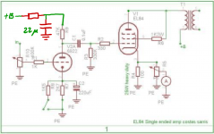
I am curious to know what function do the capacitors have that I marked in green and pink?
I know that the capacitors that I marked with green are 22uF 500V the pink ones I don't really know.
What type of capacitors would you recommend to replace them with? I assume electrolytic are the worst option, right?
Thanks and best regards
I am planning to upgrade my headphone tube amp by replacing capacitors and resistors.
I am perfectly capable of soldering, but I don't know how a vacuum tube amplifier works and all the components' functions.
I am curious to know what function do the capacitors have that I marked in green and pink?
I know that the capacitors that I marked with green are 22uF 500V the pink ones I don't really know.
What type of capacitors would you recommend to replace them with? I assume electrolytic are the worst option, right?
Thanks and best regards
Attachments

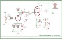
The electrolytic capacitors in pink would seem to be the 220uf cathode resistor bypass capacitors as indicated by C2 in your schematic.
Use a high quality brand like Nichicon. Make sure the caps will fit the board footprint before ordering.
I can’t really tell as a 22uf capacitor isn’t indicated on the provided schematic. It could be part of the power supply (not described by the schematic) or perhaps extra bypassing for the 220uf cathode bypass capacitors mentioned above. More eagle-eyed sleuths can better follow the PCB traces and answer this. The only thing I know is that they are also polar electrolytic capacitors so they definitely aren’t coupling caps.Ah, thank you.
Any idea what the other 2 black ones are for?
If you have a DMM that measures capacitance you can measure across one of the 22uf caps and if the value is between 220 and 270uf it’s a bypass cap for the 220uf bypass cap.
It look to me like it goes from the top of R9 to ground - a logical place for a decoupling capacitor. The other half of the voltage divider is not shown on the schematic.
The 220’s are the little ones, since they are probably 25 or 50 volt. The cathode resistor doesn’t have a ton of voltage on it.
The 220’s are the little ones, since they are probably 25 or 50 volt. The cathode resistor doesn’t have a ton of voltage on it.
I noticed that on the circuit board one of the EL84's has its pin 9 connected to pin 8. That presents a risk because pin 8 could be internally connected to an other pin, depending on the manufacturer of the EL84 being used and the date of production.
In the attached Telefunken datasheet for the EL84 for instance it says: "Free pins not to be connected externally".
In the attached Telefunken datasheet for the EL84 for instance it says: "Free pins not to be connected externally".
Attachments

For some reason I only get notified for replies via email if someone quoted me. I thought nobody answered. Thanks for your help! Also how can I put a like
on someone's post?
on someone's post?
Controversial question: would it make sense to replace these with foil capacitors? I checked there are a few foil caps with those values.the 22u with the small blue resistor are the parts of a rc-filter which connects the driver/input-tube anode to b+
Hello Yoshiitsu,
Curious as to the origin of your amp. The schematic is from Costas Sarris site, and is a copy of the Decware SE84 amp. I'm very familiar with both Costas and especially the Decware amp, but I don't recognize your PCB.
That little amp ( I use one to drive my AKG and Senn cans while my Stax rig sits idle ), is capable of excellent sonics and can be easily improved by upgrading components. I have upgraded every component in that amp and changed operating conditions on the input tubes. There's a lot that can be done.
https://www.decware.com/se84csnotes.htm
Cheers, Crazy Bill
Hey, thanks for your answer, The Person who sold it to me also built it, I am not sure if his name is Costas Sarris tho. Maybe he is because he knew a great deal about the amp and gave me suggestions on how to upgrade it. Fun fact the amplifier was listed as Decware Taboo MKIII if I remember correctly, but I was so excited that I totally missed the part where it said that it wasn't an original Decware. I just discovered it after some time in my possession.Hello Yoshiitsu,
Curious as to the origin of your amp.
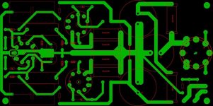
Also, it's a no-name Chinese PCB it has no specifications when he bought it (I asked him about it) might be worth ordering a new PCB with 70um copper traces. What do you guys think?
Should be around $30-40.
Last edited:
- Home
- Amplifiers
- Tubes / Valves
- What function do these capacitors have?