The further I dig the less I know...
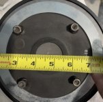
I am not too sure if it's 1.5" or 1.4".
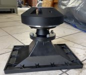
The horn has number 42011027 imprint.
I bought the speakers for cheap, so I don't expect whether or not there original.
I am not too sure if it's 1.5" or 1.4".
The horn has number 42011027 imprint.
I bought the speakers for cheap, so I don't expect whether or not there original.
Attachments

Last edited:
Since your measurement appears to be in-between 1.4 + 1.5" I would personally go with the ( cheaper ) 1.4" eminence adapter.
No matter which adapter you get > ultimately you will be using a couple of PEQ notches to smooth the raw response of your driver//horn combo.
🙂
No matter which adapter you get > ultimately you will be using a couple of PEQ notches to smooth the raw response of your driver//horn combo.
🙂
The Eminence adapter is backordered so it's on hold for now.Make sure your driver actually has a 1.5" exit ( rather than the more common 1.4" exit ).
The Eminence HA14-2 adapter is very good ( and a lot cheaper than the P-Audio ) .
The passive x-over will be implemented a couple of notch filter, will wait and see how is it response with adapter.
Once you get new measurements ( both impedance and frequency response ) using a proper adapter ( 1.4" to 2" ) then post them ( again ) within an XSim file so that I can work with them ( and help you create a passive network that's acceptable for PA > Reinforcement-Work) .
Redo the woofer Freq. response and make sure you don't change levels in-between capturing the HF vs the Woofer.
As mentioned put all those different .frd + .zma files into a single XSim file.
🙂
Redo the woofer Freq. response and make sure you don't change levels in-between capturing the HF vs the Woofer.
- Getting the relative levels between the two is very important.
- For the purpose of establishing these relative levels > take them from 2 meters away.
- OTOH for the purpose of getting the most linear frequency response , take those from 20" away ( to remove most room effects ).
As mentioned put all those different .frd + .zma files into a single XSim file.
🙂
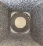
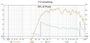
Eminence adapter installed with Initial CD measurement. How it's looked?Make sure your driver actually has a 1.5" exit ( rather than the more common 1.4" exit ).
The Eminence HA14-2 adapter is very good ( and a lot cheaper than the P-Audio ) .
Attachments

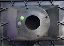
The horn has number 42011027 imprint.
I bought the speakers for cheap, so I don't expect whether or not there original.
That's a PAudio horn, not original, but most likely copied from a reputed market leader like JBL (their favourite). However, their horns usually perform like the original (to a very good extent) and are also known for being worth the money. So, nothing to worry there.
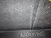
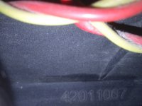
I have a couple of these horns with similar markings that, I assume, are meant to indicate where they've been copied from. For example, my copies of JBL2370A and JBL 2380A have markings that say 42011606 and 42011067 respectively. You just have to find out what horn your 42011027 stands for !!
Attachments
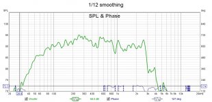
Eminence adapter installed with Initial CD measurement. How it's looked?
( With the adapter installed ) your horn//driver response looks as expected ( including the peaky response since the driver is not a "top-shelf" product ).
EarlK said:Once you get new measurements ( both impedance and frequency response ) using a proper adapter ( 1.4" to 2" ) then post them ( again ) within an XSim file so that I can work with them ( and help you create a passive network that's acceptable for PA > Reinforcement-Work) .
Redo the woofer Freq. response and make sure you don't change levels in-between capturing the HF vs the Woofer.
- Getting the relative levels between the two is very important.
- For the purpose of establishing these relative levels > take them from 2 meters away.
- OTOH for the purpose of getting the most linear frequency response , take those from 20" away ( to remove most room effects ).
As mentioned put all those different .frd + .zma files into a single XSim file.
Also, ( without changing levels ( or microphone location ) take a sweep that includes both woofer and horn//driver-combo all playing together ( with out a crossover present ) . This is necessary to attempt to figure out the drivers relative position of the drivers' Acoustic Centers (AC ) .
- Make this measurement at 2 Meters on your intended listening axis ( which many times for PA is around the bottom lip of the horn ) .
- Make this measurement at around 80db ( that way you won't hurt the horn//driver with full-range sound ) .
Post all results in an XSim file .
🙂
The horn has number 42011027 imprint.
I think this is it:
http://p-audio.co.uk/pdf/PH-3223.pdf
However, the frequency response looks fictitious to me, as all PAudio horn/driver combinations have more or less the same response.
Last edited:
Thanks for finding that out, IMO its well-made horn with good feel and touch.
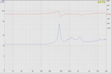
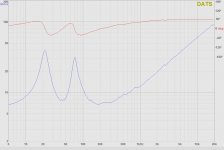
I did 2 sets of measurement on the tripod mike at 64" away 71" high and ground plane at 2 meters. I was outside and there is a bit of freeway noise in the background. I couldn't see the distinct which is better for x-over simulation.
I did 2 sets of measurement on the tripod mike at 64" away 71" high and ground plane at 2 meters. I was outside and there is a bit of freeway noise in the background. I couldn't see the distinct which is better for x-over simulation.
Attachments
Hi,
Here's one possible crossover ( it's a 3 x 3 ).

I've included the Xsim file for you to play around with.
A couple of things.
All of your woofer files were of reversed polarity. One can see that by simply looking at the impulse response .
You "zeroed" all your impulses within REW >> I would have preferred them not zeroed as that way I can compare "Zeroed to Xsim's minimum-phase determination as one form of double check. Zeroing in REW essentially forces the drivers into a form of minimum phase.
Anyways, here's a starting point crossover >> play with resistor values ( R1 + R4 ) to achieve best fit at crossover when you actually build something up.
🙂
Here's one possible crossover ( it's a 3 x 3 ).
I've included the Xsim file for you to play around with.
A couple of things.
All of your woofer files were of reversed polarity. One can see that by simply looking at the impulse response .
- ( acquire that habit of checking before continuing on with any design work )
- One doesn't want to start the design process with drivers of unknown polarity.
- I flipped the polarity of the woofer within REW ( though it didn't export flipped//corrected > which was a learning experience for me 😉 )
- Keeping ones polarity known and correct when trying to figure out the Acoustic Center offset is critical.
You "zeroed" all your impulses within REW >> I would have preferred them not zeroed as that way I can compare "Zeroed to Xsim's minimum-phase determination as one form of double check. Zeroing in REW essentially forces the drivers into a form of minimum phase.
Anyways, here's a starting point crossover >> play with resistor values ( R1 + R4 ) to achieve best fit at crossover when you actually build something up.
🙂
Attachments
Training hat On
The frequency curve looks good, fairly flat within ~4dB.
I usually have it at 0dB on mod sensitivity (on xsim) is there a reason you have it at 5dB?
Would 1300Hz x-over causing a bit of 15" woofer beaming issue?
The CD fs=430Hz and it's 2" why not at 2Xfs? this give the woofer match better on sheer horse power of the CD.
YES, I made an error on the polarity will measure again oops .
How do I "not zeroed " in REW?
thanks
Sorry! You're right ( I used an older file ).
I made a mistake in bumping up the sensitivity of just the woofer by 5db ( but not doing the same to the horn driver combo ).
- Therefore the padding for the HF circuit will need adjusting.
You can lower the crossover point ( if you want downto 860hz ) when you design the next version 😉 I did say this was one possibility.
- Some beaming for PA work can be an advantage in reducing feedback with stage instruments ( FWIW ).
In REW, one needs to use a timing reference to get distance info. There's an option to turn-on "Timing Reference" using an internal "chirp" that must be directed to the HF combo. You'll need to research the matter further for a more complete set of directions.
🙂
Here's a quick pass at a 900hz crossover.

It uses more components > see if you can reduce that number when you have a go at it.
I've also included a 1100hz crossover as "modE" ( just for the heck of it ).
I bumped up the sensitivities of both the woofer and horn driver by 5db ( to get a better guess at what the system sensitivity will be ).
🙂
Attachments
Big thank to you EarLK I learn more along the way.
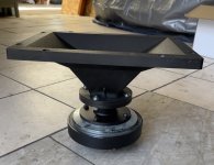
I prefer the 900Hz which I think give the woofer do less work so more SPL than 1300Hz one, both give >6ohms impedance easy on amp. I will need to gut the old x-over and build CD magnet supporter because the extension of the adapter.
I prefer the 900Hz which I think give the woofer do less work so more SPL than 1300Hz one, both give >6ohms impedance easy on amp. I will need to gut the old x-over and build CD magnet supporter because the extension of the adapter.
- Home
- Loudspeakers
- Multi-Way
- help creating x-over for 15" PA cab