Yeah that's better. You can also check the throat, it can be the same case. Sometimes the number of slices can be decreased as a result, which can also provide a better meshing. At the same time all of this effectively decreases the total number of BEM elements.
Adding a scripted enclosure won't change this so it's still important. That's why I mention it.
Adding a scripted enclosure won't change this so it's still important. That's why I mention it.
Last edited:
I tried the previous box with an increased edge radius (25mm instead of 15mm). Interestingly it's almost not any better, at least from what I can see -
(Edit: OK, it's slightly better)


(Edit: OK, it's slightly better)
Last edited:

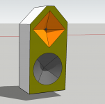
The waveguide morphed into a rectangle. It's not that easy 🙂
This is due to the added wall length at the corners, which adds more area to perimeter n and also changes ratio perimeter n to perimeter s. Oval/round and square devices are therefore not easily translatable and must be reconstructed anew.
…I tried the previous box with an increased edge radius (25mm instead of 15mm).
What I found interesting is that 25 mm already is showing reasonable effects in mitigating cabinet width diffraction. A 40 to 50 mm rounding could be much more effective than previously assumed.(Edit: OK, it's slightly better)
I guess some of the ripples in higher frequency are due to not-perfect termination (lower q). With a relatively small asymmetric device, there is this trade-off: If termination is extended, the wall length of the vertical axis is getting quite short, which could lead to loss of pattern too early for a reasonable crossover frequency. What I mean by wall length here is the section which governed by perimeter n.
If the baffle is somewhat wider, one can further optimize for more even SPL with extended termination.
Tried a bigger enclosure - horizontal, vertical UP and vertical DOWN (all normalized to 0 deg):


Maybe adding a woofer diaphragm would not be difficult. Both could solve in one go after all.
Maybe adding a woofer diaphragm would not be difficult. Both could solve in one go after all.
The vertical results look a bit off. When I worked on the waveguide in infinite baffle mode, post #9045, this range was not visible. For horizontal response, the widening of the pattern in the cossover region is moderate and as intended. But the vertical response between 1–3 kHz is too wide, while the higher frequencies seem to exhibit a narrower pattern than what was simulated on IB. Wouldn't even know how to optimize: with correct crossover, there will be nulls right where the widening looks most problematic at the moment. Still, it seems that vertical axis needs tweaking.
The down shows the point I was making before that the bigger flat baffle area can control the directivity lower, particularly in something that loses directivity due to the smaller dimension. The lack of directivity from the guide then lights up the baffle more so the diffractive hump gets bigger.Tried a bigger enclosure - horizontal, vertical UP and vertical DOWN (all normalized to 0 deg):
Now I'm curious what happens to the far-field vertical polars of a free standing horn when placed near a separate woofer enclosure. It should not be a problem to add a second enclosure to the project.
I guess fluid means "main diffraction hump" seen on any baffle at about frequency whose wavelength is the baffle dimension, just above baffle step. Pattern narrows due to edge diffraction makes opposite polarity "back wave" emerge from the edge, which shows up as constructive interference on-axis and destructive off-axis at the baffle dimension wavelength and easily seen when the transducer is center of the baffle dimension. On-axis the flipped and 1/2wl delayed "back wave" would sum constructively with direct sound but on the off-axis the opposite edge "back wave" is out of phase as the delay is 1 wl. Your example doesn't have the source centered on the baffle so both UP and DOWN show different response. Anyway, the important bit is that the taller baffle supports longer wavelength and below frequencies the waveguide lost its directivity now radiate along the baffle and gets diffracted, and the "main diffraction hump" is the first to appear. If there is no flat baffle, then the directivity and "baffle support" are about the same wavelength and this doesn't happen at least not so strongly. Long wavelengths just go around causing no diffraction interference while shorter are guided nicely by the waveguide. A reason axisymmetric waveguide would perform better on system like this, less sound to vertical edge and less diffraction. Or more like there isn't much benefit using asymmetric waveguide on any system?🙂
Yes please, include second enclosure with free standing waveguide! It would be interesting to see the difference, how much space there would have to be between the objects in order to reduce this, or is it even worse than if both woofer and waveguide share the baffle? Hard to say, wavelength is quite long at xo in relation to the physical dimensions but both waveguide and box are most likely as big if not bigger than the wavelength. Don't forget to model both waveguide response in vicinity of woofer box as well as woofers response when there is waveguide nearby. They both need to play at crossover and the dimensions are so that the diffraction easily happens on both, unless dipole woofer with strong side null.
Yes please, include second enclosure with free standing waveguide! It would be interesting to see the difference, how much space there would have to be between the objects in order to reduce this, or is it even worse than if both woofer and waveguide share the baffle? Hard to say, wavelength is quite long at xo in relation to the physical dimensions but both waveguide and box are most likely as big if not bigger than the wavelength. Don't forget to model both waveguide response in vicinity of woofer box as well as woofers response when there is waveguide nearby. They both need to play at crossover and the dimensions are so that the diffraction easily happens on both, unless dipole woofer with strong side null.
Last edited:
Something like this, you can see that it is not quite as clean as the horizontal. There isn't enough mesh resolution in the cabinet for the high frequencies. When you do it yourself it should look similar but with less hash. The same thing happens the bigger flat panel affects the vertical up and down which to me was at least unexpected at the time.Now I'm curious what happens to the far-field vertical polars of a free standing horn when placed near a separate woofer enclosure. It should not be a problem to add a second enclosure to the project.

I'm not sure I follow. Here's a direct comparison of V-Up (0 -> -90) and V-Down (0 -> 90) for the two cases:
The V up is not the same in both cases, the flat baffle area below the waveguide upsets both the vertical up and down. The bigger dimension down controls the radiation better to a lower frequency but the diffractive hump that is seen in the 1k region is stronger and pervades diagonally upwards. The taller and thinner the baffle the more pronounced this becomes.
There is still some evidence of the hump in the V up but it is less.
It was this quite different response from an infinite baffle that made sheeple somewhat disappointed with his waveguide in a box. The asymmetry in this guide causes the vertical to behave worse in a real box than other sims might suggest.
Yes, this was unexpected. But I was not most concerned about the diffraction hump. As I have also noted above, I found that the radiation pattern above diffraction hump had slightly changed, becoming more narrow. It was obvious to me that there was more optimization needed, which without proficient ABEC and Fusion360 skills, I was not seeing myself able to do.
From a practical standpoint, there is two and a half questions for me now:
1) Is the vertical dimension of about 19.5 cm not good enough? It is much more extended than some typical 90 x 60 PA waveguides, which come at only 12 cm height. I was expecting a significant performance difference with + 6.5 cm vertical dimension. However, these waveguides use no termination, which means more length is assigned to the walls.
2) Why does the vertical pattern appear to be narrower above diffraction zone than as it was simulated in IB mode? The pattern kind of gets squished in an angle, more and wider energy at the lower frequencies and higher than expected directivity / less energy in the higher frequencies. I wonder if it is possible to mitigate this with a different set of parameters.
2.5) Although the normalized pattern does not change when less energy is applied via a crossover, the interference zone does change the pattern quite a bit. The role of vertical nulls here is another variable, which makes things a bit tricky. What if they effectively annihilate energy caused by the vertical diffraction hump? Then, removing energy in this frequency area by waveguide design could even cause problems.
Out of interest, I checked how much rounding is used in a commercial product like the Genelec S360. They use a radius of 3 cm.
How much of the size is given over to termination will have an effect on the smoothness vs polar control. You can see the negative effect of the loss of vertical directivity higher in frequency as the size and shape of the baffle become more significant.1) Is the vertical dimension of about 19.5 cm not good enough? It is much more extended than some typical 90 x 60 PA waveguides, which come at only 12 cm height. I was expecting a significant performance difference with + 6.5 cm vertical dimension. However, these waveguides use no termination, which means more length is assigned to the walls.
Directivity comes from diffraction in a finite baffle that is not there in an infinite one. Certainly the parameters can be altered to optimize the response via enclosure shape but it is not always intuitive how that could be done. I imagine that there will be much experimentation and data available from more people when mabat releases the new Ath, in the same way it did for the other things it can already do.2) Why does the vertical pattern appear to be narrower above diffraction zone than as it was simulated in IB mode? The pattern kind of gets squished in an angle, more and wider energy at the lower frequencies and higher than expected directivity / less energy in the higher frequencies. I wonder if it is possible to mitigate this with a different set of parameters.
I don't know but one of kimmo's suggestions is that the tweeter should have little to no on-axis baffle gain below the crossover.2.5) Although the normalized pattern does not change when less energy is applied via a crossover, the interference zone does change the pattern quite a bit. The role of vertical nulls here is another variable, which makes things a bit tricky. What if they effectively annihilate energy caused by the vertical diffraction hump? Then, removing energy in this frequency area by waveguide design could even cause problems.
OK, now I think I see what you mean.
- BTW, this is rounded vs chamfered (H, V, D), the last thing I wanted to implement for this release. I still need to update the User Guide, then it will be available.


- BTW, this is rounded vs chamfered (H, V, D), the last thing I wanted to implement for this release. I still need to update the User Guide, then it will be available.
- Home
- Loudspeakers
- Multi-Way
- Acoustic Horn Design – The Easy Way (Ath4)