Hi All,
1st time poster!
I'm running an old NAD 1600 and 2 NAD 2600's...sometimes bridged sometimes not.
I replaced the speaker relays in both 2600's a few months ago and now they work great!
The 1600 has now started to have the left channel louder than the right. I have confirmed this buy running each 2600 separately with a different pre-amp.
I haven't opened it up yet to take a look but am wondering, could it be something as simple as bad solder joints on the pre-in rca connectors?
or is it just time for a re-cap?
Any suggestions of caps if thats the case? I did find this kit from the UK
https://www.audio-high-store.com/product/nad-1600-upgrade-kit-audio-capacitors/
Any suggestions are greatly appreciated!
Foo
Wondering the same.
Guess u would come better out, buying caps from digikey or similar.
Bought recap set for my 3400 amp, and they don't provide a list of which caps to be changed. So i run short....
Guess u would come better out, buying caps from digikey or similar.
Bought recap set for my 3400 amp, and they don't provide a list of which caps to be changed. So i run short....
Clean all the switches, pots, connectors first, including those on the rear panel, before any soldering.Hi All,
1st time poster!
I'm running an old NAD 1600 and 2 NAD 2600's...sometimes bridged sometimes not.
I replaced the speaker relays in both 2600's a few months ago and now they work great!
The 1600 has now started to have the left channel louder than the right. I have confirmed this buy running each 2600 separately with a different pre-amp.
I haven't opened it up yet to take a look but am wondering, could it be something as simple as bad solder joints on the pre-in rca connectors?
or is it just time for a re-cap?
Any suggestions of caps if thats the case? I did find this kit from the UK
https://www.audio-high-store.com/product/nad-1600-upgrade-kit-audio-capacitors/
Any suggestions are greatly appreciated!
Foo
Check the EPL in/out jumpers on the rear panel as well.
Last edited:
Gain is usually determined by resistors. However it could be affected by the tone control caps if the tone-defeat switch isn't active, so check its not something to do with the tone controls.
If its basic gain mismatch there are many resistors in the signal chain that might be at issue, or perhaps an active component has failed or partially failed - differential troubleshooting between the channels is the way to narrow down where the difference is. However I first check the balance control has symmetrical resistance.
I'm assuming the difference in level isn't accompanied by obvious distortion or skewed frequency response...
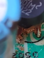
I saw a nad 1600 video in youtube and recommend removing the brown goop in ribbon and electrolitics, it gets conductive. I did so and s small channel seems to go away.

I proceeded to change all the regulator caps ( 3 regulators). Also, I retouched the solder joints a and deox the motorized pot ( it has a port to apply the oil). The motorized pot works great now (it was not working before). As the channel imbalance has been cleared.
So your problem had nothing to do with the thread title?I finished the cleaning and removal of the goop and seems the imbalance in gong
Last edited:
i recapped the main power supply and the 12 and 5 volt regulators bulk caps, all with some part of burn marks, so i think it did.
These are shared between channels - how can their failure cause a problem in just one channel resulting in loss of volume - what makes you think like that?i recapped the main power supply and the 12 and 5 volt regulators bulk caps,
Not that renewing capacitors would not be good but like you yourself wrote - the problem disappeared after cleaning the board from "goop"...
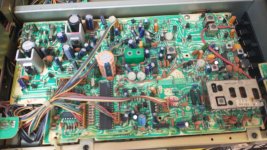
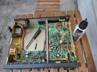
That is exactly what I stated. I got a very dirty unit, both inside and outside. After inspection , the input caps of the main bridge and two 78xx were bloated and burned.They were recapped. Above and beyond that, cleaning the goop around the board and pots removed all the channel imbalance, noise and brought back all the remote control functions.
Next is the recap of the signal path of the opamps on the preamp and tone board, will not do the tunner board.
Final objective of a recap is to improve the quality of the gear, and unless you ungoop it first, a total recap will be partially moot.
I was trying to convey that cleaning the board and removing all goop might be a good idea before starting the replacement of the caps on the signal path. In my case, it has cured many problems, but I still desire to get the most out of the unit, so I will keep posting when I do the signal path recap.
Attach files
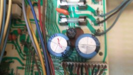
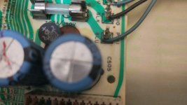
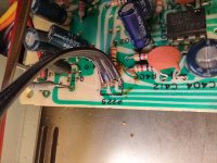
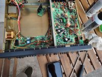
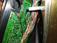
Before: when I got the unit it was dirty and greasy inside and outside, from a heavy smoker house with a lot of nicotine type grease inside. After the first cleaning the imbalance was gone. You can also see the silicon over the ribbon connectors placed after the removal of the goop.
Before: when I got the unit it was dirty and greasy inside and outside, from a heavy smoker house with a lot of nicotine type grease inside. After the first cleaning the imbalance was gone. You can also see the silicon over the ribbon connectors placed after the removal of the goop.
Attachments
-
 nad1.jpg401.1 KB · Views: 50
 -
 IMG_20221211_161358512.jpg273 KB · Views: 53
 -
 IMG_20221211_161410962_HDR.jpg175.5 KB · Views: 48
 -
 IMG_20221211_161430672.jpg380.8 KB · Views: 54
 -
 IMG_20221211_162412748_HDR.jpg646.6 KB · Views: 50
 -
 IMG_20221211_163555730_HDR.jpg322.8 KB · Views: 48
 -
 IMG_20221211_165554416.jpg157.4 KB · Views: 51
 -
 IMG_20221211_171620295.jpg728.6 KB · Views: 41
 -
 IMG_20221211_173213380.jpg219.5 KB · Views: 44
 -
 IMG_20221211_174211379.jpg569.1 KB · Views: 40
 -
 IMG_20221212_095343839_HDR.jpg347.5 KB · Views: 56
 -
 nad1.jpg401.1 KB · Views: 58
Last edited:
- Home
- Source & Line
- Analog Line Level
- NAD 1600 Re-Cap