Gladly take your word for it -I've never looked into the details, although I assume it's some form of variable rate (as in shallow initial rolloff increasing to higher order via the notch)? I've done a couple of notched filters to hit (initial) high order slopes in the past; these days I figure it's probably more trouble than it's worth, albeit interesting.Indeed, and it's amount is not obvious. Sixth order I think, on the Elsinores.
However. Apologies for the brief OT!
Thanx, just strated reading the thred, i was going to post the link.Dave's pdf on the subject.
http://www.planet10-hifi.com/downloads/Dual-Driver-Wiring.pdf
I have done work on 3 & 4 drivers, but some of the 3s can be a can of worms and it was set aside for awhile.
I do gave the drivers, and the box will be small enuff to 3D print, a shunt cap across 2 of the A6 run in series.
Something like this but with 3 drivers
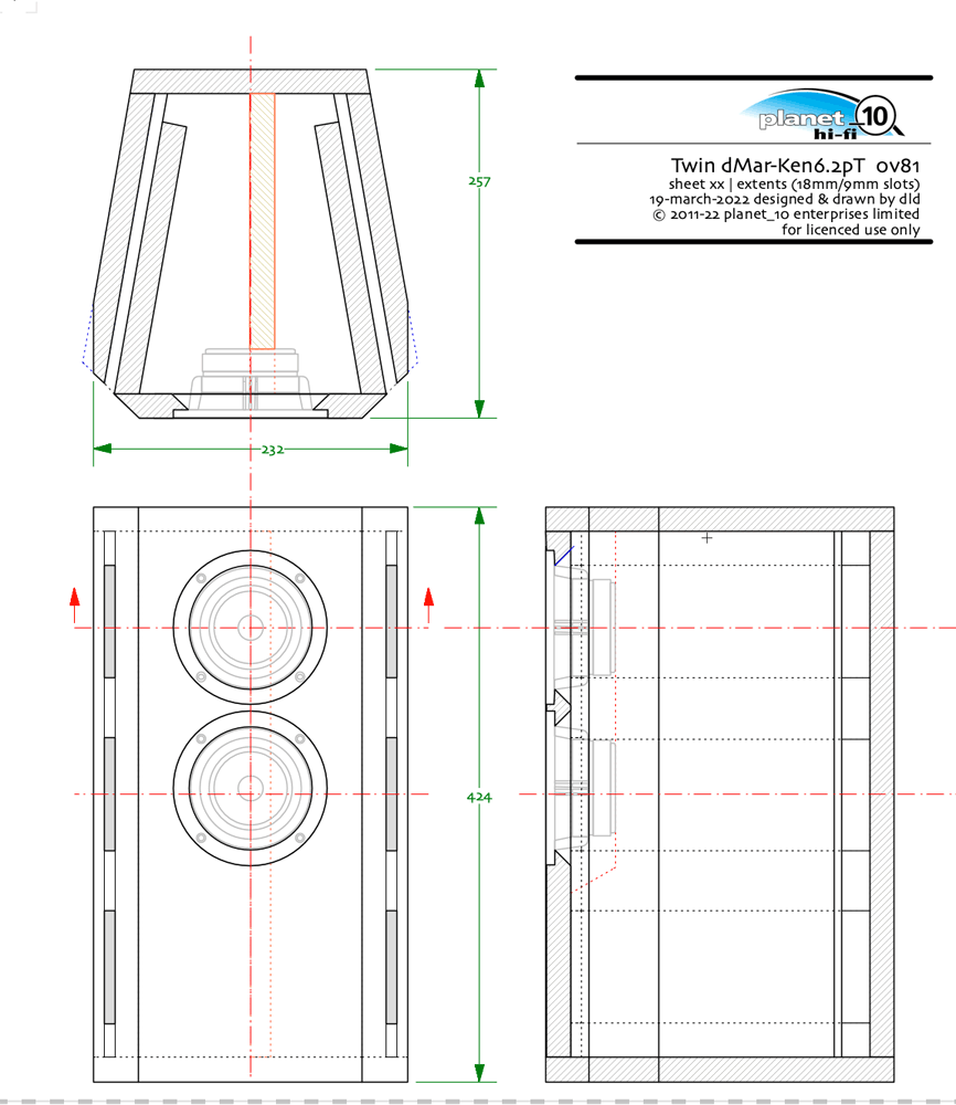
dave

...although it won't serve for addressing step loss...
The case when you have a low Rout, but if you have a current amp it will indeed do step loss, and as the amplifier impedance starts to approach the cross-over you will get partial step-loss compensation.
dave
I inquired some time back about using multiple 0.5 drivers, wired in parallel to each other, but in series to the main driver with a shunt cap. The idea being, tripling the radiating surface area but with only a small increase in impedance at lower frequencies. While I've never done anything with this in the real world. Simulations show it should provide baffle step. In another thread about the subject, a member here, posted a link to his build on another forum in which he used this concept. https://www.canuckaudiomart.com/forum/viewtopic.php?f=21&t=35200 . Just to be clear, I'm not claiming that I have invented anything. That member's build predates my interest on the subject
What whould be the difference between A and B, then?To answer the original cabinet question, I don't see any problem with twin drivers series wired in a common closed enclosure. But remember that each driver only sees half the common enclosure volume. They are working together at low frequencies, which is where you would expect any unwanted interaction.
Unfortunately I cannot neither simulate A, nor build B.
Thanks
Assuming the following:
Measured performance should be essentially identical. Internal standing waves and reflections will be different, but that`s another matter.
- A = B
- B1 = B2 (B sub-volumes)
- The capacitor is sized so the corner frequency is around or above the upper mass corner (2 * Fs / Qts)
Measured performance should be essentially identical. Internal standing waves and reflections will be different, but that`s another matter.
Interesting formula, which i didn't know.! It seems 100uF iworks well here:Assuming the following:
- A = B
- B1 = B2 (B sub-volumes)
- The capacitor is sized so the corner frequency is around or above the upper mass corner (2 * Fs / Qts)
Measured performance should be essentially identical. Internal standing waves and reflections will be different, but that`s another matter.
PLUVIA 11
DC resistance Re = 5.4 Ohm
total Q factor Qts = 0,29 (Qms=1,797, Qes=0,351)
resonance frequency fs = 39 Hz
cutoff frequency with C=100uF and R=5.4Ohm => 295Hz
upper mass corner (2 * Fs / Qts) => 268Hz
Can you explain the formula?
Mass corner Fhm is the nominal -3dB point on the mathematical IB curve where the driver transitions from the rising response (acceleration) bandwidth, into the mass-controlled (flat) bandwidth. It varies of course with effective Qts, where effective Qts' = Qts + any series R in the circuit, or the amplifier output impedance).
I can't think of a way to model driver air pressure interaction in a common enclosure with a simulator.
Just have to guess really.
Curt Campbell uses common enclosures with series and paralllel wired basses.
Personally I favour series wired. The currents are identical through the two basses, especially at low frequency which is the bit where excursion and impedance is large.
Makes sense to me. Paralllel wired could get into trouble, especially with a filter in front. Er, IMO.
I don't know a better word. I am trying to describe ygg-it's concerns that the two fullrangers in a common enclosure will interact via air or sound pressure.
Complicated by a 45 or 90 degree phase difference.
This is the topic of the thread.
It's kinda obvious that there might be an interaction between the two drivers. Lynn Olson went to the trouble of constructing separate chambers for his parallel-wired Ariel speaker.

When you push one driver in, the other will push out by air pressure.
How it works electrically with series or parallel wiring is a deeper problem. Which I tried to solve. But always leads to arguments.
Complicated by a 45 or 90 degree phase difference.
This is the topic of the thread.
It's kinda obvious that there might be an interaction between the two drivers. Lynn Olson went to the trouble of constructing separate chambers for his parallel-wired Ariel speaker.
When you push one driver in, the other will push out by air pressure.
How it works electrically with series or parallel wiring is a deeper problem. Which I tried to solve. But always leads to arguments.
Phase differences caused by the cap on one driver with the two drivers in parallel - causes acoustic phase differences in pressure inside the box - which causes non coherent interactions between them - ie the 'rocking'..?
Lynn Olson went to the trouble of constructing separate chambers for his parallel-wired Ariel speaker.
Lynn provided independent lines for the Ariel units, but not because the drivers were wired in parallel, Steve. In fact, he's on record as being highly suspicious of series-wired drivers sharing a vented volume, but somewhat less so for parallel.
The independent lines in the later versions of the Ariel arose for a completely different reason. I don't know how much you know of quarter-wave design, but if you look at the V2 and V3 enclosures, you'll see they used a 'Y' shaped line, where the upper & lower drive units had an independent line, which were then merged about halfway down the cabinet. Unfortunately, that meant that two physically different pathlengths were merged (since that to the upper driver was longer than that to the lower) which can cause all kinds of undesirable interactions unless very carefully modelled or empirically built off a large amount of measured data, neither of which were available to Lynn in the early 1990s. Hence, with the V4 enclosure, he shifted to physically independent lines of matched length, which fixed that particular issue, at the price of complexity.
Last edited:
You can't really do this with parallel wired drivers, since the capacitor will be shunting both units.Phase differences caused by the cap on one driver with the two drivers in parallel - causes acoustic phase differences in pressure inside the box - which causes non coherent interactions between them - ie the 'rocking'..?
Assuming we're talking about loudspeakers in operation, not if they're wired in the same electrical polarity they won't. They are receiving the same electrical signal, so assuming they are so wired (as they better be, since you'd have zero net displacement & output from the box otherwise) then they will move in the same direction, which is dictated by the current. This isn't analogous to mechanically pressing in one driver with your hand: the correct analogy would be to press both in with your hand at the same time, which is the mechanical equivalent of delivering the same electrical current to each unit.When you push one driver in, the other will push out by air pressure.
There is a way.You can't really do this with parallel wired drivers
With just a single shunt cap and no other components? I stand corrected, as I've obviously missed something.
- Home
- Loudspeakers
- Full Range
- Help me to understand this Series configuration