Hi everyone, i want to know something... i've some 0.47uf(microF) 275VAC X2 rated polypropylene capacitors & i want to use one across the transformer primary (live to neutral) for RF suppression. It's a 220VA EI core transformer, primary 220VAC. My question is do you think the value is right? i mean can i use 0.47uf here? Or lower value is more suited?

Hello,Hi everyone, i want to know something... i've some 0.47uf(microF) 275VAC X2 rated polypropylene capacitors & i want to use one across the transformer primary (live to neutral) for RF suppression. It's a 220VA EI core transformer, primary 220VAC. My question is do you think the value is right? i mean can i use 0.47uf here? Or lower value is more suited?
Personally would not use a cap that is rated that close to the incoming (220v). Peaks can be higher and any spikes much higher. Also, make sure this cap across the incoming power is after a fuse.
IHMO: There are people who put much larger caps (microfarads) across the incoming power, never heard a positive result of any decently controlled testing indicating that it actually helped. But need to be very careful as the potential for shorts and fires go up considerably and could created a shock hazard if not done well. Double insulation would be ideal. FWIW
Hello,
Yes, it is rated OK. But, still should be behind a fuse from the incoming. Many of us go with higher ratings to make sure to avoid problems. If it doesn't get stressed and break, you don't have to fix it. This is DIY, you are free to use better rated parts or those that are just rated for what you are doing. Your decision.
Yes, it is rated OK. But, still should be behind a fuse from the incoming. Many of us go with higher ratings to make sure to avoid problems. If it doesn't get stressed and break, you don't have to fix it. This is DIY, you are free to use better rated parts or those that are just rated for what you are doing. Your decision.
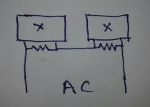
Nice 🙂 Should i use a ballast resistor between them? What's the recommended value & power rating?!If you put two in series, they will stand 550VAC.
Generally, you would tack a resistor across each cap. ½W for the voltage rating, I usually use 300k but there's no real reason for that number. 1M would probably work fine as film caps don't tend to have much leakage.
'X' value resistor across(in parallel) each cap? & two in series?? I've some 470k 1/2w resistor, 1M also.
I mean like this? or only one resistor across both capacitor? Btw i heard that ballast resistors required when use two cap in series.
Attachments
Last edited:
There is no need for overdesign with a X-class capacitor, and putting two in series will mostly reduce their efficacy without improving the safety level. One of them will always wear out faster than the other (loss of metallization due to self-healing), and the asymmetry will get worse and worse with time, because the weaker one will see higher voltages.
A fuse upstream is always good, and if you want to increase the filtering effectiveness, you should consider adding an inductive element rather than simply increasing the C value
A fuse upstream is always good, and if you want to increase the filtering effectiveness, you should consider adding an inductive element rather than simply increasing the C value
Alright, then i think i should use only one across the power switch to prevent it from arcing(after the 1amp slow blow fuse). But the value 0.47uf is too high i think. How about 1-10nf Y cap?


I would use a class X 100n across the mains, (live to neutral) after the fuse and 1n0 class Y contact suppression on the power switch if you think the switch contact quality is suspect and not up to usual mains power.
The problem is i don't have more than 275vAC rated x cap. All smps i've, full of same 275AC caps.
Putting a cap directly across a switch is a problem, both for the switch and the capacitor: when the cap is charged, the short-circuit current is ~unlimited (it is in fact limited by the technology of X-caps and their shallow metallization).Alright, then i think i should use only one across the power switch to prevent it from arcing(after the 1amp slow blow fuse). But the value 0.47uf is too high i think. How about 1-10nf Y cap?
View attachment 1033648
This can damage the switch contacts, and the cap metallization where it connects to the shoopage terminals. This will accelerate the wear of both components.
If you connect the cap across the transformer, the current will be limited by the characteristic impedance of the mains wiring, typically between 30 and 80 ohm.
For direct connection across the switch, ready-made, X-rated RC combinations exist, and they are probably the best solution.
Y caps are OK for X jobs, but they rarely come in values higher than 10nF
- Home
- Amplifiers
- Power Supplies
- X2 cap across the mains