I just acquired a Hafler DH-101 (serial number 1020167) and am about to launch into a comprehensive refurbishment of the electronic components. I have no interest in doing any of the much discussed mods, nor do I want to make any alterations to the original design. I plan to change capacitor and resistor construction as is feasible (film capacitors and metal film resistors), and likely will replace the rear RCA jacks. I have verified that this unit has the DH-106 upgrade in place. However, I'm confused about two things I see on the P-4 board.
First, according to the Component Values list in the manual, C1 is a 220pF 1000V Disc capacitor. However, in the location on the actual P-4 where the layout diagram shows C1, neither channel has the capacitor present. It doesn't look like the capacitors were removed from these locations but rather there were never any capacitors in these locations to begin with. Could this be a later production run modification?
Second, in locations C2 and C11, the Component Value list and the P-4 layout diagram shows a single 10uF 3V Tantalum capacitor in these locations. However, the actual board has two 10uF Tantalum capacitors installed in series (+ to +) apparently to create a virtual non-polar Tantalum capacitor. My question is, if I were to replace these with film capacitors, what should the capacitance be? The normal formula for capacitors in series would yield 5uF for this arrangement. Or because this is a "non-polar" Tantalum, is the capacitance calculated differently? I would prefer to use is single film capacitor in these locations, but will do a direct replacement of the Tantalums with electrolytics if necessary.
Thank you for any assistance anyone can provide on these questions.
I got my DH-101 at an audio show at the Nassau County Coliseum in (or about) 1982, later got the moving coil pre-pre. My #3 son now has the unit, I took sons #1 and #2 to the show!
If I recall, most of the RIAA components were fine..
40 years later there are 4.7uF polypro caps to replace the tants.
If I recall, most of the RIAA components were fine..
40 years later there are 4.7uF polypro caps to replace the tants.
My confusion about the Tantalum capacitors stems from two parts of the P-4 diagram (attached). The diagram clearly show the trace for 2 capacitors that will end up in series, however, it show a single capacitor bridging from beginning to end with the same capacitance as each of the pair of installed capacitors. Lacking any other information, I would have to assume this was just lack of attention to detail in the diagram.


C1 is used as a compensation capacitor for the moving magnet phono cartridge. Together with R1 it prevents "ringing" at high frequency.First, according to the Component Values list in the manual, C1 is a 220pF 1000V Disc capacitor. However, in the location on the actual P-4 where the layout diagram shows C1, neither channel has the capacitor present. It doesn't look like the capacitors were removed from these locations but rather there were never any capacitors in these locations to begin with. Could this be a later production run modification?
Second, in locations C2 and C11, the Component Value list and the P-4 layout diagram shows a single 10uF 3V Tantalum capacitor in these locations. However, the actual board has two 10uF Tantalum capacitors installed in series (+ to +) apparently to create a virtual non-polar Tantalum capacitor. My question is, if I were to replace these with film capacitors, what should the capacitance be? The normal formula for capacitors in series would yield 5uF for this arrangement. Or because this is a "non-polar" Tantalum, is the capacitance calculated differently? I would prefer to use is single film capacitor in these locations, but will do a direct replacement of the Tantalums with electrolytics if necessary.
Thank you for any assistance anyone can provide on these questions.
C2 protects the phono cartridge from current flowing into the cartridge.
You can find hundreds of radial film caps at Mouser or DK for C2 and C11.
Thank you, very cool to know. But then, that begs the question, why is my DH-101 (and others I've seen pictures of) missing C1? On mine, it looks as though it was never present in the first place judging by the condition of the trace-side where C1 is located. FWIW, mine does not have the DH-102 Preamp feature. I tried my DH-101out with a moving-iron cartridge (Bang & Olufsen turntable) and the sound was very good, but I'll admit it was at relatively low volumes via headphones.
I put in an order at Mouser. I decided to go with a single 5uF film capacitor for C2 and C11 instead of a pair of electrolytics, or a single bi-polar electrolytic.
I put in an order at Mouser. I decided to go with a single 5uF film capacitor for C2 and C11 instead of a pair of electrolytics, or a single bi-polar electrolytic.
The capacitance value for C1 will vary with the cartridge used. The cartridge manufacturer will specify the correct capacitance. The capacitance of the cabling from cartridge to preamp should be considered part of the total capacitance load as well. So each system needs a particular capacitor in the preamp that Hafler has no way to foretell.
So if one were to measure/calculate the total capacitance load, would that be the appropriate value for the C1 capacitor? This assumes, of course, that there is only one turntable in use, or only one cartridge in use across two of the same kind of turntables, or the unlikely result that both turntable/cartridge/cable combinations have the same capacitance...
C1 is determined as follows:
Look up the specifications for your cartridge and see what capacitive load the manufacturer recommends. The attached catalog page from Stanton indicates their moving magnet cartridges should be loaded with 275pF.
Measure the capacitance of the cabling from cartridge to preamp. Suppose it is 100pF. Then the value of C1 should be 275pF - 100pF = 175pF.
This capacitor value is not extremely critical. If you connect more than one turntable or more than one cartridge to the preamp at various times, shoot for a middle value for C1 that is reasonably close for each setup.
Attachments
You also must account for the approximate capacitance of the input circuit. The Hafler manual explains this, at least the DH-110 manual does. The DH-110 had lead sockets installed to allow the cap to be changed for different cartridges.
Well, are your push buttons really still good? Mine only lasted a few years, so besides a few cap moda and maybe a bit more i the PS, replacing the selector, power and monitor switches would be on my list.
It was a very good amp. I made the mistake of being talked into an APT Holman as an upgrade which it was not!. Then got a Nakamichi which was in fact even better. Totally different price range though.
It was a very good amp. I made the mistake of being talked into an APT Holman as an upgrade which it was not!. Then got a Nakamichi which was in fact even better. Totally different price range though.
The switches do appear to be just fine. However, if there weren't, the only recourse would be to try to rebuild the switches, as direct replacements are not available. Is that not correct?
I will be mating it with my Hafler DH-220 amp (which is also going to undergo a complete component rebuild). I want the DH-101 to be the system preamp until I am able to rebuild my Hegeman HAPI-2. As absolutely no documentation exists about the components in the HAPI-2, I'll be taking a much longer time to get it up and going. So in the meantime, the DH-101 gets the job....
Yes, I've already started with the De-oxit. And I'll be disassembling the front completely so I can do a thorough cleaning and lubrication of all those parts.
And thank you all for the information surrounding the C1 capacitors. I have a firm plan now on how to approach adding those capacitors.
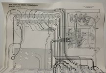
There is a further twist on the C1 story. According to a spreadsheet at https://docs.google.com/spreadsheets/d/1hvdkCcaFyQri_itAl2JF9IO1B2QGGzeNElr2GSn7xXI/htmlview there was an update to the DH-101 manual in 1979. From 1978 to 1979 C1 was moved from PC4 (after the selection switch) directly to the input jacks of Phono 1. Since C1 was no longer switched between Phono 1 and Phono 2 C30 was added to the input of Phono 2. This is confirmed by the pictorial from an Ebay auction for the 1979 manual, attached. The 220pF capacitors are in the upper left, mounted to the RCA jacks. Your DH-101 may have these capacitors mounted to the RCA jacks.
An additional change is the removal of the suicide capacitors, C22 and C28. Those should be removed for safety reasons if they are populated in your DH-101. Originally they were mounted to the AC outlets.
An additional change is the removal of the suicide capacitors, C22 and C28. Those should be removed for safety reasons if they are populated in your DH-101. Originally they were mounted to the AC outlets.
Attachments
Thank you, I do recall seeing disk capacitors attached to the the input jacks, so I will have to take a closer look at those for capacitance matching.
Suicide capacitors? That conjures up all kinds of interesting images. I assume their function would be to protect the rest of the circuitry in the event of some sort of spike? What are the safety reasons to remove them; are there "safer" capacitors that might replace them?
Suicide capacitors? That conjures up all kinds of interesting images. I assume their function would be to protect the rest of the circuitry in the event of some sort of spike? What are the safety reasons to remove them; are there "safer" capacitors that might replace them?
The suicide capacitors are connected from both sides of the AC mains to the chassis. Hafler removed them because that connection is dangerous when the chassis is ungrounded. Check that your DH-101 looks like the upper right in the pictorial (AC Outlets wiring). Do not replace capacitors C22 and C28 if they are missing.
Thanks for the clarification. I did check and the suicide capacitors have indeed been removed from the DH-101 that I have.
I plan to experiment with different capacitor values for the ones mounted to the Phono input jacks to see what works best with the B&O turntables I have. The cartridge specifies 225pF, and the cable tests out at about 100pF, so I plan to install a pair of 100pF MLCC's on one of the Phono input jack sets to start with. I might also install a pair of 50pF MLCC's on the other Phono input jack set to see how it compares.
I plan to experiment with different capacitor values for the ones mounted to the Phono input jacks to see what works best with the B&O turntables I have. The cartridge specifies 225pF, and the cable tests out at about 100pF, so I plan to install a pair of 100pF MLCC's on one of the Phono input jack sets to start with. I might also install a pair of 50pF MLCC's on the other Phono input jack set to see how it compares.
- Home
- Source & Line
- Analog Line Level
- Hafler DH-101 Electronic Refurb