This Christmas and around the New Years eve I was left completly alone with a friend's cat that i had to feed and I could take my time measuring about a hundred germanium transistors, mainly ac 180, ac181 , ac187 and ac 188 .Then I started some simulations for some buffers, but I had to use silicon models.In the beginning I considered a simple op amp driving a diamond buffer.I've both included the buffer inside the op amp loop and then excluded the buffer out of the loop, but I wanted to hear what germanium transistors have to say outside the loop.Then a very simple buffer idea stroke me when finding that a diamond buffer topology can't properly compensate germanium transistors due to the natural leakage and hfe differences between npn and pnp gèrmañium transistors. Moreover the new buffer proved to be 20...30db more linear than a diamond buffer in simulations just around -100 db THD in all audio range up to 20 khz using silicon trz models so I considered the global feedback useless and I was right.
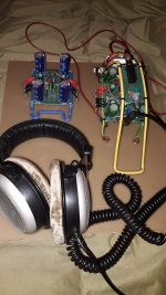
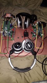
The listening tests with the buffer outside the op-amp loop...as linear as can possibly be , no " germanium compression"...It sounded like the best tpa6120 headphones amp to my ears right from the begining and the transistors were completly cold.Although i did plenty of simulations for 32 ohms loads with very good results too i could only test my 250 ohms headphones.
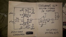
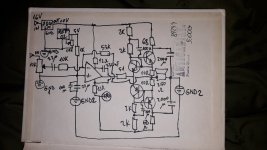
Anyone willing to sort germanium transistors will find this simple schematic rewarding for all the efforts.Some inductors might be useful here and there.
Of course you can try a rail bootstraped version for higher output powers too..
I have to thank to Sergiu, a good friend of mine who got me into this crazy idea that germanium can sing, to Molly for inspiration and to Franzm for Hartsuiker's design idea.
What I really didn't expect was to measure less than 10mv output dc offset to real ground...
I used first njm4556 , then lm4562 as they work reasonably well at +-3V DC.I'll try lm6152 next as it works at even lower voltages and I have some around, but I'm really open for rro low voltage op-amps suggestions .
Unfortunately due to some problems I have with my computer i can't post the simulations.
The listening tests with the buffer outside the op-amp loop...as linear as can possibly be , no " germanium compression"...It sounded like the best tpa6120 headphones amp to my ears right from the begining and the transistors were completly cold.Although i did plenty of simulations for 32 ohms loads with very good results too i could only test my 250 ohms headphones.
Anyone willing to sort germanium transistors will find this simple schematic rewarding for all the efforts.Some inductors might be useful here and there.
Of course you can try a rail bootstraped version for higher output powers too..
I have to thank to Sergiu, a good friend of mine who got me into this crazy idea that germanium can sing, to Molly for inspiration and to Franzm for Hartsuiker's design idea.
What I really didn't expect was to measure less than 10mv output dc offset to real ground...
I used first njm4556 , then lm4562 as they work reasonably well at +-3V DC.I'll try lm6152 next as it works at even lower voltages and I have some around, but I'm really open for rro low voltage op-amps suggestions .
Unfortunately due to some problems I have with my computer i can't post the simulations.
Attachments


Well...can anyone help me with some hints about the best low voltage rro op-amps for audio that would consistently operate below 5v?
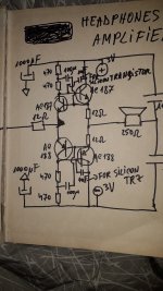
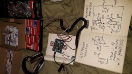
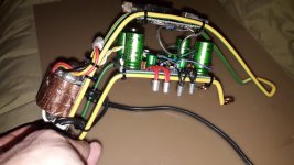
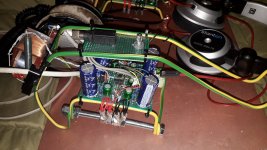
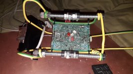
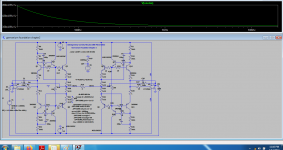
I chose to make different versions of amplifiers for 32...64 ohms and 250...600 ohms headphones.I chose a plain 10v supply , a REF02 for input ground refference and output ac ground .Same ac188/187 , no 1nf compensation capacitors as there's no oscillation with such slow transistors, global feedback(actually it doesn't make any audible difference if I let the buffer outside the feedback loop), same lm4562 for now although indeed , it picks up my phone EMI around with no shielding.I will try more op amps, but i doubt it can get any better than it already is in clarity.Lm4562 has quite low minimum supply for which it works very well unlike many of the audiophile op-amps.At 16ma per output transistor for the 250 ohms amp they are obviously stone cold. For the 32 ohms i just go with 32ma of idld current per output transistor .
Attachments

Last edited:
I did some tests replacing lm4562,lm6172, opa134, opa132, opa1642, opa2228, lm833 and some older japanese op amps but the limiting +-5v supply made only lm4562 and lm6172 acceptable yet i have to admit that opa2134 and opa2132 had the edge on the EMI while the bipolar op amps had the lowest distortions when hit hard in the base region.The datasheet of opa2134 says it' s good down to +-2.5v, but i tried it at +-5v this time and it looks like it's not able to drive the germanium emitters hard enough with lower audible distortions than lm4562.Not commenting anything about the "silky highs" after 16 hours of being awake...Opa2228 dissapointed me so far, which i didn't expect, but i might have a contact issue in the socket too as those op amps seem to be a bit loose .I need to make additional tests when fresh.

Thank you! I found some low voltage njm chips on some Presonus and Roland scraped soundcards as well and i might try them too , while i feel the weird urge to get some njm8080 from my Audient soundcard for review.I know it's a 350 bucks soundcard, but i never used it and i always dreamed to change its op-amps with some high ender ones anyway.I think i scraped a lot of working even new equipment for parts over time just for experiments, but never really regret it.I might need a new zealand visa soon though...and that is quite costly 🙂
I forgot to tell that opa1642 behaves quite similarly to lm4562 but for some reason i favour lm4562 in the mids and highs...I always felt that lm4562 has a more unified sparkling presentation than any other op-amps i tried except lm6172 which is out of this world in the mids-highs section, but i needeed to listen to it a bit until figuring out that one needs to boost the lows a bit with it and I covered it in the past. Somehow i didn't feel the lack in the lows last night with this amp so my past ideas are under review.
Actually a lot of my past ideas about anything are under heavy bombardments these days...
I still have some op-amps to test like ada4898-2 and lm6152(kinda small current capabilities though for this part) but they are on an adaptor socket that can't fit the one already in place on my preamp.Anyway i am going to finish the 32 ohms version and place a different adaptor on it for further trials and ordinary 32 ohms headpnones need lower output voltages anyway so my lm6152 chips might perform acceptably well when driving some emitters.
I'm still amazed of how stable the 3200v/us lm6172 is.It never produced any oscillations on any pcb, old equipment or prototype model i've tried it on while it shows a similarly EMI sensitive behavior as lm4562.
For the moment i can't risk buying any new op-amp or other electronics cause this new war situation at our borders might bring real famine and economical disasters in the very near future and food shortaged seem to be the next "best thing" to be tried so i feel this hobby of mine will soon come second, but for the moment I'm happy with what I've already achieved. Yet you can try this circuit yourself just because I think it deserves some attention.
If i wouldn't have tried it i would've probably thrown useless theories about too low FT leaky transistors at anyone talking about germanium transistors just because i could.Thankfully that I feel will never happen.As anyone can see I equally praise high quality silicon semiconductor chips and global feedback when I can .I preffer agnosticism over atheism for as long as I never saw proof of God's inexistence 🙂 Those russian and allies military guidance systems we all fear might have a lot of germanium as well...We just need to be prepared for collecting them from the scraped metal yard when the time has come and find a better use for death delivery instruments. Thermal noise is a music in itself...hopefully not the one left after our self destruction would confirm the most feared variant of Fermi's paradox theory.
If people would only play music on germanium instead rockets guidance systems maybe the germanium technology wouldn't be too expensive and leaky...
One guy said once that if we's all play tube amps the wold would be a better place to live and we wouldn't care about their electrical efficiency.
Last edited:
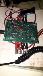
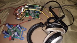
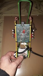
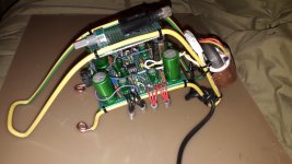
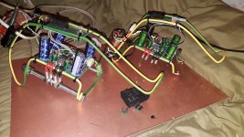
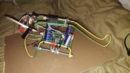
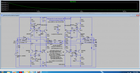
I finished the 32 ohms version too...really minor differences between the two 250 and 32 ohms versions.Just doubled the current, improvised heatsink and bigger caps.
I also changed the op-amp socket with one that can accomodate squared pins for smd adapters.
For the moment i had only some modest 64 ohms headphones to test it but i was satisfied with the results.Being basically the same circuit as the 250 ohms circuit swaping op-amps had similar results.
Unfortunately higher slew rate op-amps like ada4898-2 and lm6152 were impossible to be used without
compensation .I didn't dive too much into the causes, but the output of ada4898 stuck instantly to one of the rails while lm6152 had about 300mv output offset which would have asked me to set the bias very differently .lm6152 was very unstable anyway in my circuit so i ruled it out just out of convenience.
I didn't have a perfect supply transformer do i needed to use a 47 ohms resistor in series on its output to keep the lm7810 cold without using a heatsink which wasn't easy to accomodate on my pcb.
The only real gain that i see from this last model is the minimalist design i ended up with for cooling the ac187/ac188 although the idle current i used here (about 30..35ma ) didn't do much to increase the heat.
It will probably serve me later for driving proper 1...2w 4ohms speakers if i get to find aluminium 8mm screws, but that's serious task here.
Attachments
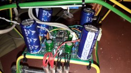
I ended up replacing the 68 ohms collector resistors with 12 ohms ones and the base content became perfect with j-fet op amps opa1642 and opa2132 while the output offset is now 0...2mv.
Many of you wouldn't probably consider that I can fully enjoy this type of music on germanium transistors, but I do!
Many of you wouldn't probably consider that I can fully enjoy this type of music on germanium transistors, but I do!
Last edited:
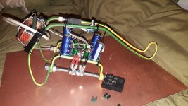
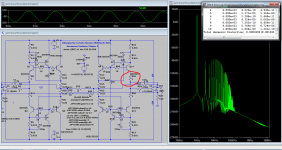
Chapter 2... 4...8 ohms load.
Just a bit more into class B domain and I thank @Molly once more for giving me some more insights on Bloomley design with his sim model found here:
https://www.diyaudio.com/community/threads/the-blomley-class-b-amplifier.322744/page-8#post-6981177
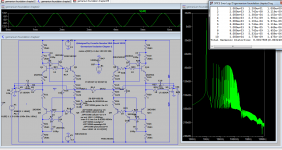
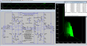
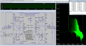
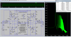
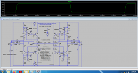
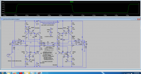
I tried to make the Blomley amp simulation work as in Hartsuiker cofiguration driven by an op-amp but I wasn't sucessful enough to get the triplets in class B while my cofiguration allowed for better results apparently.
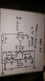
Of course the sim down below was done with silicon trz as i don't have the models for ac180...187.
Most probably I'll be using only one final pair of silicon trz driven by the same germanium pair so that r8, r11, r19, r20 can be replaced with 1n4148.
R16, R17, R46, R48 are NTC resistors in case of using germanium for final pairs.
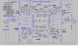
AC180=181 aren't too great with respect to dissipation...so i doubt I'll be using them as final pairs .I was also thinking of going only with an ubalanced design as i like it more and allows me to use ac180 and 181 as final pairs too for obviously less output power but better control, yet having 4 amplifiers will let me choose more wisely when finished.
Just a bit more into class B domain and I thank @Molly once more for giving me some more insights on Bloomley design with his sim model found here:
https://www.diyaudio.com/community/threads/the-blomley-class-b-amplifier.322744/page-8#post-6981177
I tried to make the Blomley amp simulation work as in Hartsuiker cofiguration driven by an op-amp but I wasn't sucessful enough to get the triplets in class B while my cofiguration allowed for better results apparently.
Of course the sim down below was done with silicon trz as i don't have the models for ac180...187.
Most probably I'll be using only one final pair of silicon trz driven by the same germanium pair so that r8, r11, r19, r20 can be replaced with 1n4148.
R16, R17, R46, R48 are NTC resistors in case of using germanium for final pairs.
AC180=181 aren't too great with respect to dissipation...so i doubt I'll be using them as final pairs .I was also thinking of going only with an ubalanced design as i like it more and allows me to use ac180 and 181 as final pairs too for obviously less output power but better control, yet having 4 amplifiers will let me choose more wisely when finished.
Attachments
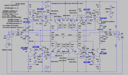
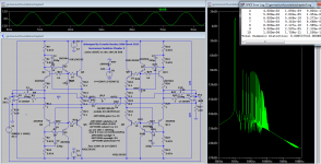
Analyzing this schematic again i found that a maximum theoretical supply voltage of +-8v would be allowed for operating with those types of germanium transistors on 4 ohms load as the dissipation is double than it should be while +-6v would be the safest one...being essentially a class b amp it might work with +-12v but i'm not sure for how long...
Before I commit to build one of the two variations...could anyone share his experience about which of the two feedback topology would be more suitable to an inductive load ? I'd go anytime with germB versions if I wouldn't fear the back EMF.My past experience with electrostatic speakers told me that version germB is quite capable but i have no valuable experience with tough inductive loads in this topology. By the way THD on 4 ohm loads is just double the THD on 8 ohms but that's resistive...Would the usual Zobel the one I should trust to solve the problem with any of the topologies ?
Attachments
-
 germA1k.png42.6 KB · Views: 137
 -
 germB1k.png43 KB · Views: 124
 -
 germA10k.png40.2 KB · Views: 119
 -
 germB10k.png42.3 KB · Views: 118
 -
 germAstep.png36.8 KB · Views: 117
 -
 germBstep.png35.2 KB · Views: 127
 -
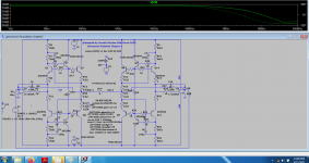 germAbode.png40.4 KB · Views: 119
 -
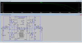 germBbode.png25.8 KB · Views: 122
 -
 germAnoise.png36.9 KB · Views: 113
 -
 germBnoise.png36.2 KB · Views: 127
Anyone?...should I change the title of this topic? I will use germanium transistors for the first two transistors and maybe silicon trz for the last two transistors , r8, r11, r20, r26 might also be replaced with some sort of temp sensitive device if r16 , r45 won't be the ones to do the temp compensation, but my main question would be which of the two topologies would be better with an inductive load just because i don't really know how to sim a speaker.
Last edited:
It may be baffling that the topic evolved outside headphones amplification domain but I saw here some 20 watts/8 ohm amps advertized to be the holly grail of headphones amplification ...If there's no other way to get some feedback i'll try making a new similar topic in the right section of the forum.
- Home
- Amplifiers
- Headphone Systems
- Germanium foundation- Chapter1