HI Everyone
I'm Ale from Italy
My english is anything but perfect.
This is my second audio project and I know this is a strange way to do a sub.
I decided to build a sub for my coaxial synergy PA tops built in this thread with the help of many diyaudio guys
https://www.diyaudio.com/community/threads/2x12-and-1-4-coax-cd-synergy.373100/
My main limitation is dimension: 970x750x550mm ( my car trunk dimensions).
My goals are:
1- high spl that can match the tops (105-ish db/1m and about 3kw each)
2- not very low extension needed because I will use only for live rock music so from 45-50hz to 100HZ.
3-possibilty to transport and assemble secondary flare for bigger venues.
I absorbed some ppsl design principles reading a good part of the big ppsl enclosures thread here even if my design is push push.
Usually the plenum depth need to be the smallest possible but with my data I can lower the highest peak down to 100hz using deeper plenum.


With 18ds115-8 I can use little box volume.
The driver chambers are separated.
The triangular BR ports are 440cm2 total (but I can modify easily) with 50m/s velocity at 6800w.
I want to create guides in the wood for the ports to shift it inside and outside and tune differently when I use 2 flare or not.
The secondary flare can accomodate the sub box for compact transportation.

Now i would decide which position is better for left br port. (last picture).

Do you see any problems in this design??
I really appreciate you opinion and suggestions!!!!
Thank you very much
Ale
I'm Ale from Italy
My english is anything but perfect.
This is my second audio project and I know this is a strange way to do a sub.
I decided to build a sub for my coaxial synergy PA tops built in this thread with the help of many diyaudio guys
https://www.diyaudio.com/community/threads/2x12-and-1-4-coax-cd-synergy.373100/
My main limitation is dimension: 970x750x550mm ( my car trunk dimensions).
My goals are:
1- high spl that can match the tops (105-ish db/1m and about 3kw each)
2- not very low extension needed because I will use only for live rock music so from 45-50hz to 100HZ.
3-possibilty to transport and assemble secondary flare for bigger venues.
I absorbed some ppsl design principles reading a good part of the big ppsl enclosures thread here even if my design is push push.
Usually the plenum depth need to be the smallest possible but with my data I can lower the highest peak down to 100hz using deeper plenum.
With 18ds115-8 I can use little box volume.
The driver chambers are separated.
The triangular BR ports are 440cm2 total (but I can modify easily) with 50m/s velocity at 6800w.
I want to create guides in the wood for the ports to shift it inside and outside and tune differently when I use 2 flare or not.
The secondary flare can accomodate the sub box for compact transportation.
Now i would decide which position is better for left br port. (last picture).
Do you see any problems in this design??
I really appreciate you opinion and suggestions!!!!
Thank you very much
Ale

HI guys!
thank you
I almost finished the proto box and I will test before glue.
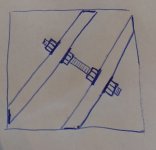
I would make the plenum very stiff. my ideas are:
1- wood wall in the middle of the plenum, but my fear is that can change the sound (or raise the modal resonance frequency of the diagonal dimension?)
and can be difficult to assemble with the glue.
2-(picture)some big 20-22mm threaded rods with self-locking nuts or with few drops of soft threadlocker, easier to assemble and phonotransparent.
The fp14000 arrived.
I think the cable from amp and sub will be 10meters.
In your opinion is better to bridge the amp and go with the two drivers in parallel or use 1 channel for 1 driver?
Thank you
Ale
thank you
I almost finished the proto box and I will test before glue.
I would make the plenum very stiff. my ideas are:
1- wood wall in the middle of the plenum, but my fear is that can change the sound (or raise the modal resonance frequency of the diagonal dimension?)
and can be difficult to assemble with the glue.
2-(picture)some big 20-22mm threaded rods with self-locking nuts or with few drops of soft threadlocker, easier to assemble and phonotransparent.
The fp14000 arrived.
I think the cable from amp and sub will be 10meters.
In your opinion is better to bridge the amp and go with the two drivers in parallel or use 1 channel for 1 driver?
Thank you
Ale
Attachments
HI
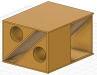
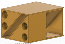
I almost finished building the cabinet
my last decision will be about shape and number of ports.
Initially I opted for 2 triangular br ports with one sliding wall for changing tuning but I tested and is very difficult to make is air-sealed.
So I would to use orange pvc pipes for house building so I can add a slice of pipe in front of the sub just inserting it in the joint of the internal pipe.
I want to decide between:
4 pipes of 140mm diam. each, lenght 49cm,615cm2 and 44m/s velocity at 6800w,
2 pipes of 200mm diam. each, lenght 46,628cm2 and 43m/2 velocity at 6800w (don't look at the position on the baffle)
Bigger than this would occupy too much internal volume, now is 160-180 liters.
4pipes like the photo will be better for air exchanging like Art said but Is worse for port eventual port chuffing???
Thank you very much
Ale
Attachments
Ale,
I don't think 1m/s is going to make an audible difference in chuffing, but the heat exchange of two vs one port might make enough difference to warrant using four ports.
Art
I don't think 1m/s is going to make an audible difference in chuffing, but the heat exchange of two vs one port might make enough difference to warrant using four ports.
Art
Can't you make a slot port on both sides? That way you can probably gain some extra surface area (for my latest designs i am around 0,5x Sd or more).
With those same slot ports on the sides they get virtually extended by the adjacent cabinet wall. I found a factor of around 0,7/0,75 to be needed to convert the similation porth length to the one in practise.
Curious about the results!
With those same slot ports on the sides they get virtually extended by the adjacent cabinet wall. I found a factor of around 0,7/0,75 to be needed to convert the similation porth length to the one in practise.
Curious about the results!
HI SmitskeCan't you make a slot port on both sides? That way you can probably gain some extra surface area (for my latest designs i am around 0,5x Sd or more).
With those same slot ports on the sides they get virtually extended by the adjacent cabinet wall. I found a factor of around 0,7/0,75 to be needed to convert the similation porth length to the one in practise.
Curious about the results!
I could do 2 big slot ports but my net volume is already limited and bigger mean deeper so I don't have enough deep space because of driver magnets
and also is difficult to make an external extension to tune it lower when I need it.
However I can test it now with pipes and take a decision before gluing
I will post tests here for sure.
Thank you
Ale
Greets!
Me?! Explain math past the very basics? Sorry, I mostly rely on the math whiz folks on the forums.
FWIW I did mine many decades ago by trial and error since I only knew the round/square/1.0:1.273 rectangular end correction = ~0.613 x internal effective radius [i.d.].
That said, as long as the HxW ratio is < 9:1 based on [long ago] heat/AC duct design, then supposedly one can design using pipe math and just subtract its end correction = radius [i.d.] x 2.227 in this case, so its 'shelf' will be somewhat shorter, but never tried it nor had any feedback from folks I mentioned it to, so caveat emptor applies.
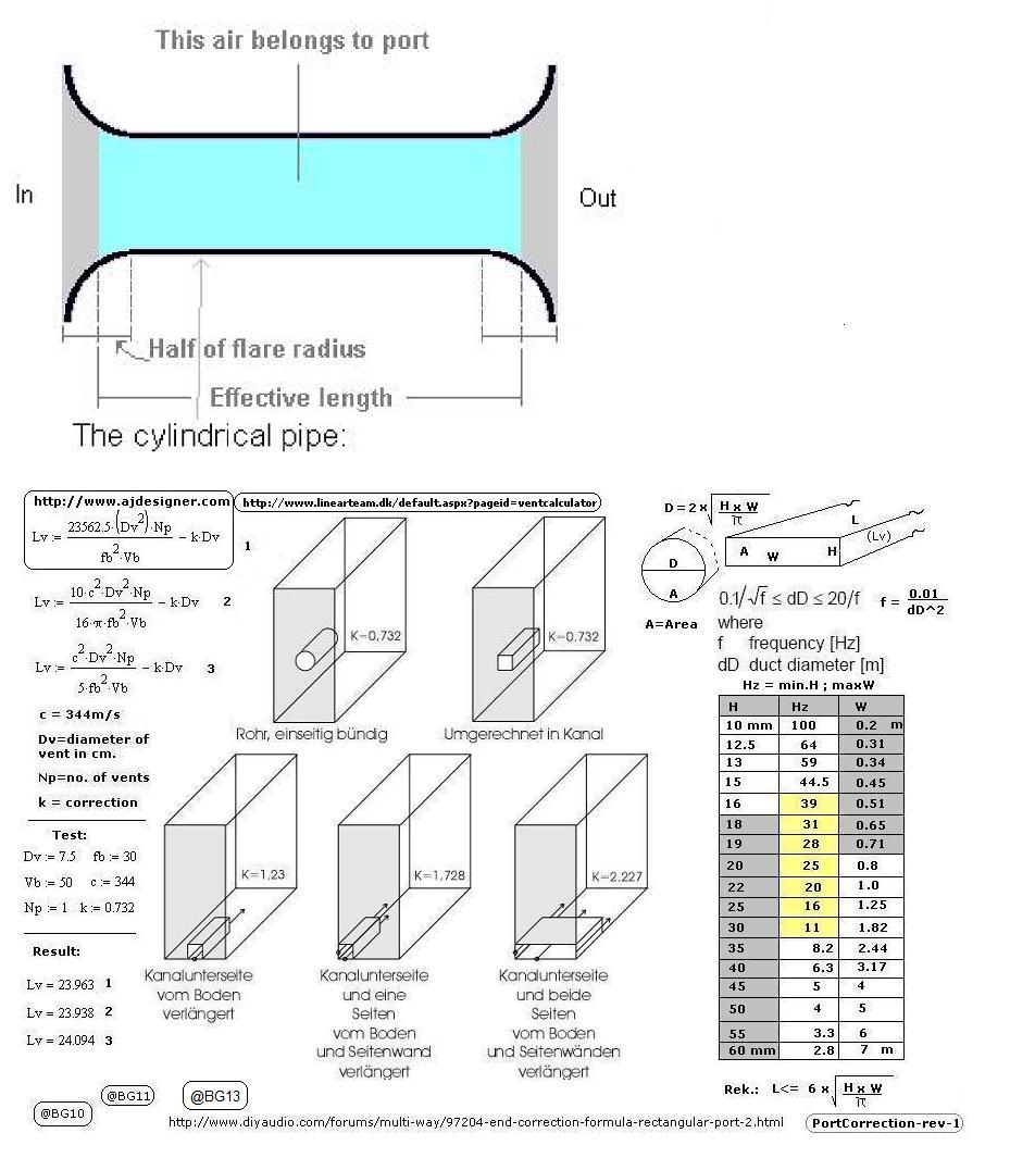
I also won't try to explain the math in the picture GM linked:HI GM
Can you explain this formula? I'm a newbie😱
Thank you
Ale
Port end correction factor “K” value increases from a standard value of 0.732 (one end flanged by the cabinet front wall the port is located on, one end free: k = 0.425 + 0.307 = 0.732) when a port is not located some distance from cabinet side walls.
When a side, or sides of an enclosure are used as a port wall in square, rectangular or triangular ports, the port length is effectively made longer by the additional mass of air adjacent to the walls, so a port centered on one wall has a higher “K” value(1.23) than if it were away from all walls, adjacent to two walls (K=1.728), higher yet, three walls still higher, K=2.27 in the cabinet width ducted port example on the lower right above.
Because the walls make the port effectively longer, the actual port length must be reduced in length, which in turn may make more cabinet net volume available.
GM's decade old end correction in post #12 assumed both ends free: k = 0.307 + 0.307 = 0.614, he must have had the pipe hanging out the cabinet 🙂
Art
A lot older than a decade! It was in an early last century Cutler-Hammer technical library's reference chart for pipe heat exchangers.
🙂 No, just a starting point to trim the pipe/shelf to the pioneer's equal amplitude impedance peaks.
🙂 No, just a starting point to trim the pipe/shelf to the pioneer's equal amplitude impedance peaks.
Missed the "s" after "decade", time flies- it was 1871 when Lord Rayleigh first published his end correction figure.
151 years later and it's still a bit of a crap shoot to get the end correction to fit all the variables inside (and outside) a box.
151 years later and it's still a bit of a crap shoot to get the end correction to fit all the variables inside (and outside) a box.
I resemble that remark nowadays! 🙁
Never been exposed to his work beyond some math that at the time meant to avoid as a waste of time; so what is it?
Indeed! Setting on the floor or even within [3] diameters, etc., plus normally even just using the open pipe is audibly close enough until it's quite large and the only reason I was interested in it was/is due to the typically large openings required for vintage reflex alignments.
Thanks! Seems we found the same thing Googling. 😉 Now to hopefully find at least Vol. II, p.201 at the local huge used bookstore which has both a large bound and paperback 'academics' sections.
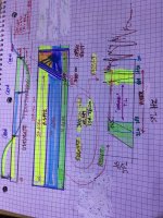
Why are these numbers always so weird?? 3.1496 or 3.1428 or 3.1416(?) and 300, 360 30? , 0.349206349 344m/sec or 345.6 m/sec or 299.972458 or 299.2?
I don’t know what’s going on here but there’s a connection to some of the stuff you can see it in hyperphysics.com pipe calculator
I don’t know what’s going on here but there’s a connection to some of the stuff you can see it in hyperphysics.com pipe calculator
Attachments
Only God knows! 😉 Me, I'm still 'scratching my head' as to how Pi, etc., math constants? were found or the incredible accuracy of ancient complex structures, etc., were designed built without falling back on space aliens.

- Home
- Loudspeakers
- Subwoofers
- Unorthodox 2x18 slot loaded PA sub