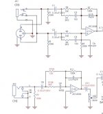
Hello This schematic is for an Ashton 60AEA Acoustic amplifier. the impedance is it 100K I think for acoustic preamp guitars.
To make it switchable input impedance between 1 or 1m5 and 100K So An electric guitar can directly in and Also a Guitar with a Piezo and no built in preamp So maybe thinking even 2M
I do not know if the 4558 will tolerate the value changes and the circuit will work with this idea?
Looking at the schematic I would make The alterations to R1, R2, and R9.
Also I noticed on the first channel R8 Is also a 100k resistor to ground before the first gain stage And question whether this should be altered also?
Thankyou for any advice.
Attachments
Last edited:
The tip of TRS-Jack is connected to C1? In that case input impedance is 10kOhm instead of 100kOhm. This hole circuitry is suitable more for some symmetric, active driven instrument than a passive hi-z output. I would not try to rebuild this but insert an active DI-box with hi-z input and low-Z output.
Thankyou, I should have done some more research about input impedance before posting this. I’m not sure why I thought it was so simple when there are a lot of calculations involved.The tip of TRS-Jack is connected to C1? In that case input impedance is 10kOhm instead of 100kOhm. This hole circuitry is suitable more for some symmetric, active driven instrument than a passive hi-z output. I would not try to rebuild this but insert an active DI-box with hi-z input and low-Z output.
You are welcome!Thankyou, I should have done some more research about input impedance before posting this. I’m not sure why I thought it was so simple when there are a lot of calculations involved.
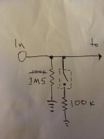
Just a quick observation about the OP second circuit - the switch should be on the ground-side of the resistor so its not riding the signal.