New step 3 🙂Swap the main filter caps (10000uF), B+ for B- side and see if the +ve rail drops when the power amp board is attached. Could be a duff main filter cap causing a droop.
They are brand new but it;s simple to check, on the other hand the -44v line is good <sigh> I know i'm learning, I don't have to like it
Andy
I’d put in the spare amp board and see if there is still a problem. Will eliminate the Power Amp board or confirm it…New step 3 🙂
They are brand new but it;s simple to check, on the other hand the -44v line is good <sigh> I know i'm learning, I don't have to like it
Andy
J
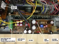
But its not as Shiny 🙂, although I did change out the diodes for some reasonI’d put in the spare amp board and see if there is still a problem. Will eliminate the Power Amp board or confirm it…
J
The real issue is with the wire wrapping. I'm always having to bear that in mind with minimum number of disconnects.
So you see another issue with the supposed reliability of V-fets. It's probably a simple fix but most 'shops would have quit before now - because you can't actively diagnose anything. So when these were more common - straight to landfill
I'd be grumpy but this is a very first world problem
Andy
A soldering iron is the best tool here. I could not thread the old wire into the wrap tool without it fraying, so solder and heatshrink….
Modern connectors should be much more reliable than the 70’s ones, so there is that option.
Modern connectors should be much more reliable than the 70’s ones, so there is that option.
Help needed then - I'm looking for PCB crimp connectors, 5mm pitch, preferably with gold contact surfaces can anyone suggest a candidate? 5mm for ferrules is fine but that won't fly on the main board.Modern connectors should be much more reliable than the 70’s ones, so there is that option.
HELP!!
So today's efforts:
As a last fling, I re-wrapped the connection on the power amp board and the fault re-appears. So I guess I know where it might be now. However, I already checked those transistors... Also during this test some "vapour" appeared near either C412 or C413 or R419 so that's nice - it was the old PSU board but "Noted" I don't think the voltage drops enough to put it the wrong side of the -44v rail, but R419 is right in the current flow.
At this point, I'm not confident in the amp board - at least not enough to ever expose V-Fets to it, so I think it's time for a big deep breath and take the fact I have a spare as a blessing. Frying Pan and Fire?
Andy
- Different PSU board with Wurth screw connectors (fine here)
- Disconnected the blue link wire for -Vcc on the main amp board
- -92 V now 'there' so I think the fault must lie on that channel (Right, I think)
- I now get +89v and -92v not ideal, but within the "no Vfets fitted" window
As a last fling, I re-wrapped the connection on the power amp board and the fault re-appears. So I guess I know where it might be now. However, I already checked those transistors... Also during this test some "vapour" appeared near either C412 or C413 or R419 so that's nice - it was the old PSU board but "Noted" I don't think the voltage drops enough to put it the wrong side of the -44v rail, but R419 is right in the current flow.
At this point, I'm not confident in the amp board - at least not enough to ever expose V-Fets to it, so I think it's time for a big deep breath and take the fact I have a spare as a blessing. Frying Pan and Fire?
Andy

BREAKTHROUGH
It looks like a frayed wire issue was the problem. I was preparing to unsolder the wire wrap terminals so I could avoid re-wrapping, when I spotted a single strand from one post to another (60)-1 to (60)-2 on the amp board. Not actually wires I've touched but there you go.
At one point I was convinced it must be a solder bridge I'd left, turns out it was, sort of
I've addressed that, and all voltages now check out, nothing smokes (nice)
Voltages below are relative to earth at the speaker terminal and after the speaker relay has kicked in
20v line was 19.98v and "HT" was 96.1v
and off the PSU board
Blue : -85.0
Orange : +84.9
Yellow : -47.94
Green : -48.73
Time to pop the "new" PSU board in and re-check - the resistors aren't semi cooked on that one.
Andy
Attachments

Well done on spotting the errant strand of wire. Soon be time for the vfet installation and biasing. Not long until you will be playing music through it.BREAKTHROUGH
It looks like a frayed wire issue was the problem. I was preparing to unsolder the wire wrap terminals so I could avoid re-wrapping, when I spotted a single strand from one post to another (60)-1 to (60)-2 on the amp board. Not actually wires I've touched but there you go.
At one point I was convinced it must be a solder bridge I'd left, turns out it was, sort of
I've addressed that, and all voltages now check out, nothing smokes (nice)
Voltages below are relative to earth at the speaker terminal and after the speaker relay has kicked in
20v line was 19.98v and "HT" was 96.1v
and off the PSU board
Blue : -85.0
Orange : +84.9
Yellow : -47.94
Green : -48.73
Time to pop the "new" PSU board in and re-check - the resistors aren't semi cooked on that one.
Andy
Well you know how like to draw things out 😀 - and an early start tomorrow means I can't get into vfets today. But the 'new' PSU board does indeed function as intended [insert Bill and Ted guitar riff] and a photo to detail it for when I forget later...Well done on spotting the errant strand of wire. Soon be time for the vfet installation and biasing. Not long until you will be playing music through it.
Just about lost a month, I'd feel embarrassed, but my previous experience is connectors that can't be inverted and silkscreens that are correct.
Next:
- Check the pre-amp actually works - given the previous wiring "oops" the whole board might be dead I haven't really checked yet other than the input voltages are good; hopefully that means 'all OK' rather than 'failed open circuit'
- Throw some irreplaceable Vfets at it and set bias.
I have a set of Rank 53's that came out of this amp (or at least an eBay TA-5650) but service bulletin says not suitable?! I wanted to keep the R55's for the TAN-5550 @jonboylaw any pointers on that?
There's starting to be a slight whiff of optimism here.
Andy
Attachments
Regarding the rankings, the bulletin does state 54-57s for the 4650 and 5650, however I have seen 5650’s with 53s.
When I tried a set of 53’s in my 4650, it would not bias, I.e no voltage on the test point. I would say, set the max vgs and instal the vFets and see if one channel will bias. If it does then you are good to go.
When I tried a set of 53’s in my 4650, it would not bias, I.e no voltage on the test point. I would say, set the max vgs and instal the vFets and see if one channel will bias. If it does then you are good to go.


Now that's taking it to another level!Parts just came in today after yellow zinc plating. Hopefully, I can start assembling after all the Ecaps are recapped.
Time to up your game Andy 🤣Now that's taking it to another level!
So as it turns out it wasn't the wiggly wire...
BUT I have found the problem or rather the cause. Everything is spot on until I connect the amp board to the heat sink using the Vfet fastening holes. (Heat sink already connected to the chassis) but one screw through any of the Vfet mounts and -ve rail volts plummet after a few seconds (they start higher though, around +/-97 vs +/-84 ish)
What else, if the audio input plug is removed from the amp board there is a significant offset; +97v vs -75v even when the thing is not screwed together, reconnect it (and associated grounds?) everything balances out again
Back to plan A? swap amp boards and see what happens?
Andy
At the moment I'd be happy with any sort of game 🙂Time to up your game Andy 🤣
You are using the isolation mounting HW when you screw into the vfet mounts right? If the screw shorts to the heatsink then it may well be the problem.At the moment I'd be happy with any sort of game 🙂
It's just as it comes.... Ah! oh! oooooooh I seeYou are using the isolation mounting HW when you screw into the vfet mounts right? If the screw shorts to the heatsink then it may well be the problem.
Attached .gif suddenly very appropriate
Oh dear, oh dear, oh dear... Thanks Jon - No Vfets = no Mica. I just realised why/how the mounting system works - air gaps!!
Andy
Attachments

Air is a great insulator!It's just as it comes.... Ah! oh! oooooooh I see
Attached .gif suddenly very appropriate
Oh dear, oh dear, oh dear... Thanks Jon - No Vfets = no Mica. I just realised why/how the mounting system works - air gaps!!
Andy
At least we are getting to the crux of the (non) issue. I never used the vfet mounts during testing, only the top board mounts so never considered this at all.
We will have this board up and running in no time now.
🥳
- Home
- Amplifiers
- Solid State
- Complimentary ramblings AKA another Sony TA-5650 V-Fet thread