Hi there!
I have done a deepdive in individually addressable RGB leds. I want to build a graphic visualizer. The simplest way at this point seems an arduino with analog inputs and analog line level filters. There are 6 analog inputs, so I want 6 bands. Since the audio fidelity is not important, I am thinking of a very simple 1st order RC filter, but I can't find if that would be suitable for line level audio. Anyone who can help me out?
Thanks!
Google "op-amp state variable filter". These circuits take 3 op-amp per band, but they have the flexibility to do what you want. Particularly, the Q is adjustable for each frequency. To do "bandpass" you need at least a 2nd order filter. Yes, there are single op-amp circuit available; perhaps you can find by Google "op-amp bandpass filter" ;')
Be sure to show the "images", for circuit schematics.
Be sure to show the "images", for circuit schematics.
Isn't the order just how steep the filter is? You obviously do need two filters, a lpf and hpf. Variable isn't needed since I have 6 set bands. I'm going to look into it, thanks!
Here's a three channel version, which can be extended to six by scaling the capacitors.
https://www.alexajakob.com/blog/2021/05/23/color-organ.html
And another example.
https://makezine.com/projects/easy-led-color-organ/
https://www.alexajakob.com/blog/2021/05/23/color-organ.html
And another example.
https://makezine.com/projects/easy-led-color-organ/
The first one looks good, but also pretty complicated. There also is an amp stage, is that needed or can I skip that stage if I go line level in? 1 volt peak would be just fine, that's 1/5th of the 1024 "steps" possible, plenty. And is it possible to get away with passive filters? Like this https://www.electronics-tutorials.ws/filter/filter_4.html ? That would make the process waaaay easier, and I would prefer that
You can make your own design, but that is starting from scratch instead of just copying an existing design.
These are about as simple as possible. Color organs usually only have three channels, since that works well.
With passive filters, six channels is too many, and three is about the maximum for passive.
Line level sources do have to be able to drive the circuit properly.
Here is an example of a circuit with more channels. It requires more elaborate filters.
https://www.tinaja.com/glib/musclrog.pdf
Last edited:
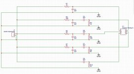
The big difference is that I am not going to make the same thing. I am going into the analog in on an arduino, reading that value and converting it to individual addressable led's (EDIT: so instead of light intensity, the intensity is conveyed by more leds that are lit, for example 5 rows of 30 leds, a loud sub sound would light all lights an in the first row, a soft sub sound would light only 5. The LEDs are driven by the arduino, not the audio voltage). I have quickly worked out a schematic, very simple RC passive filters. Would this work? I have not included an amp stage in the schematic, but any simple amp would do probably.
EDIT2: This filter has a 6dB/octave slope, which might not be steep enough so I could double the rolloff. 12dB/octave should be fine
EDIT2: This filter has a 6dB/octave slope, which might not be steep enough so I could double the rolloff. 12dB/octave should be fine
Attachments
Last edited:
An input buffer is necessary due to the low filter impedances, and it also could have some gain.The big difference is that I am not going to make the same thing. I am going into the analog in on an arduino, reading that value and converting it to individual addressable led's (EDIT: so instead of light intensity, the intensity is conveyed by more leds that are lit, for example 5 rows of 30 leds, a loud sub sound would light all lights an in the first row, a soft sub sound would light only 5. The LEDs are driven by the arduino, not the audio voltage). I have quickly worked out a schematic, very simple RC passive filters. Would this work? I have not included an amp stage in the schematic, but any simple amp would do probably.
EDIT2: This filter has a 6dB/octave slope, which might not be steep enough so I could double the rolloff. 12dB/octave should be fine
Second order passive filters are poor.
Good point! Do you have any recommendations for schematics I could use? And what do you mean with "poor"? The sound quality doesn't matter since it's purely to measure intensity, phaseshifting doesn't matter either. In any case, thanks a lot with the help so far already 🙂An input buffer is necessary due to the low filter impedances, and it also could have some gain.
Second order passive filters are poor.
A standard op amp, with input at + terminal, two resistor feedback to - terminal, can drive 2k.
So scale up the Rs (and Cs down) appropriately. The 20 ohms (even 330R) is too low to be practical.
And all those channels are in parallel, so multiply by that factor also.
Passive second order filters will have very soft knees, and a broad bandwidth (3-4 octaves).
Even a first order bandpass filter must have a like bandwidth to avoid similar problems.
I would suggest op amp active filters, there is much better performance and second order will be fine.
For more than 3 channels, second order filters are needed at a minimum to reduce overlapping.

Then I might just go with the Alexajacob one. I do have a couple questions. First, I can skip the "Volume Control" part, but what is the ".inc opamp.sub"? Also, should I only skip the LED and resistor at the end and feed that signal into the arduino, or also cut R16 and C7 and the resistors and capacitors in those spots in the other filter outputs? And what values should I change, and to which values? The bands I want are:A standard op amp, with input at + terminal, two resistor feedback to - terminal, can drive 2k.
So scale up the Rs (and Cs down) appropriately. The 20 ohms (even 330R) is too low to be practical.
And all those channels are in parallel, so multiply by that factor also.
Passive second order filters will have very soft knees, and a broad bandwidth (3-4 octaves).
Even a first order bandpass filter must have a like bandwidth to avoid similar problems.
I would suggest op amp active filters, there is much better performance and second order will be fine.
For more than 3 channels, second order filters are needed at a minimum to reduce overlapping.
0 to 80hz
80 to 250hz
250 to 1000hz
1 to 4 khz
4 to 20 khz
Once again thanks a lot for all the input!!
I just noticed the filters in the alexajakob schematic are first order filters. Do I just copy the filter part and do it twice in a row? Or should I use a whole new filter design?
Usually a level control is critical for setting the signal level just right. There's not much dynamic range in the circuit.
You'll need some space between the bands to reduce triggering both adjacent bands, because of the slow filter slopes.
The .inc opamp.sub refers to an op amp simulation model subcircuit.
The Alexajacob circuit runs on +/- 14VDC. You'll need an interface circuit to convert that to 0V/5V or 0V/3.3V.
That can be a single supply rail-to-rail op amp running on 3.3V or 5V (whichever applies) and 0V.
The interface circuit will need a bipolar DC blocking capacitor at its input, 10uF bipolar like the Nichicon UES series.
Before the interface circuit you'll need an attenuator to reduce the potential +/-14VDC signal swing,
to 0V/5V or 0V/3.3V swing. If the supply voltage is 3.3V, then attenuate by 3.3V/28V = 0.18 factor.
This could be a series 5k and a shunt 1.1k.
Try starting with the filter as shown and only change if it is inadequate for your purpose.
You should use a solderless breadboard anyway to facilitate building this as a proto easily.
I feel incredibly stupid, but this is like a completely new language to me, I did not understand 90% of it. I assumed the "Level Control" was for the output to a speaker, and since I won't use that (I have a dedicated output for this, speakers are driven from a complete different source) I thought I could skip it, but it's a level level control for the output to the bandpass filters? I don't know what an "op amp simulation model subcircuit" is either.Usually a level control is critical for setting the signal level just right. There's not much dynamic range in the circuit.
You'll need some space between the bands to reduce triggering both adjacent bands, because of the slow filter slopes.
The .inc opamp.sub refers to an op amp simulation model subcircuit.
The Alexajacob circuit runs on +/- 14VDC. You'll need an interface circuit to convert that to 0V/5V or 0V/3.3V.
That can be a single supply rail-to-rail op amp running on 3.3V or 5V (whichever applies) and 0V.
The interface circuit will need a bipolar DC blocking capacitor at its input, 10uF bipolar like the Nichicon UES series.
Before the interface circuit you'll need an attenuator to reduce the potential +/-14VDC signal swing,
to 0V/5V or 0V/3.3V swing. If the supply voltage is 3.3V, then attenuate by 3.3V/28V = 0.18 factor.
This could be a series 5k and a shunt 1.1k.
Try starting with the filter as shown and only change if it is inadequate for your purpose.
You should use a solderless breadboard anyway to facilitate building this as a proto easily.
I have read the page, and it says the outputs are in the couple of volts range. It uses a regular LED, so I assume the output won't be over 3.something volts. Do you mean converting it down to 0V(why 0V? Or is that GND?)/5V because of the voltage the arduino is running on? I don't know what an interface circuit is, nor do I know how to utilize a bipolar capacitor.
I also do not know what the signal swing is, what a shunt 1.1k is.
I have a breadboard to prototype, so that's not an issue. I am collecting the bits and pieces, but have not worked out how I can run the MATLAB program code they used (linked), so I can change the values to fit my needs.
This is not really a trivial hardware circuit, so it may be confusing to a software person.
I do think you'll need an initial level pot to adjust the circuit (and arduino) for best operation.
The LEDs conduct at 2V, and the op amps put out much more than that (+/-14V). You won't need the LEDs.
But you need an interface circuit to translate the +/-14V to levels the arduino can accept (0V to either 3.3 or 5V).
The arduino cannot accept negative input voltages, so the interface op amp shifts the zero to its range center.
The L pad voltage attenuator mentioned has a 5k series resistor, and then a shunt 1.1k ohm resistor to ground.
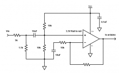
The interface circuit will look something like this. The unmarked resistor sets the gain needed.
Use a 3.3V rail to rail op amp for a 3.3V arduino, or else a 5V rail to rail op amp for a 5V arduino.
I do think you'll need an initial level pot to adjust the circuit (and arduino) for best operation.
The LEDs conduct at 2V, and the op amps put out much more than that (+/-14V). You won't need the LEDs.
But you need an interface circuit to translate the +/-14V to levels the arduino can accept (0V to either 3.3 or 5V).
The arduino cannot accept negative input voltages, so the interface op amp shifts the zero to its range center.
The L pad voltage attenuator mentioned has a 5k series resistor, and then a shunt 1.1k ohm resistor to ground.
The interface circuit will look something like this. The unmarked resistor sets the gain needed.
Use a 3.3V rail to rail op amp for a 3.3V arduino, or else a 5V rail to rail op amp for a 5V arduino.
Attachments
Last edited:
Most audio projects have been done before. Many written-up in Popular Electronics.
https://worldradiohistory.com/Archive-Poptronics/70s/1979/Poptronics-1979-09.pdfMagazine page 62 (PDF page 58)
Fig 1 shows mike or line input and level control.
Fig 2 shows filter-bank and rectifiers, and multiplex bus.
Fig 3 spreads the data across the lights. No Arduino! (This IS 1979.)
TMI: the month before this issue hit the stands, I designed and built an LED spectrum display. There was only about one difference in the core design; everybody had the same logic chips. Mine was 10x10 not 10x7 because instead of his cute case (jealous) I built into a clear cube for picture display (no digital photo-frames yet either).
I forgot one bit of the design problem. My friend got the battery backward and blew it up.
- Home
- Source & Line
- Analog Line Level
- Line level bandpass filter