I am not having my DAC board in hand, yet, but I assume it will be the schematic as given in the
PCM1794A Application Note, twice the schematic in fig. 2-4.
PCM1794A Application Note, twice the schematic in fig. 2-4.
Sorry, I gave the wrong link above. This one is correct:
DEM-PCM1792, DEM-DSD1792, DEM-PCM1794, DEM-DSD1794 EVM User's Guide
DEM-PCM1792, DEM-DSD1792, DEM-PCM1794, DEM-DSD1794 EVM User's Guide
PCB board space! Not an issue in most DIY builds, sure. But this chip is designed to be crammed onto tiny PCBs stuffed with tiny parts. It eliminates two resistors, one cap, and one op-amp section, provides a precise Vcc/2 reference voltage, and gives you a virtual ground with a very low impedance (< 8 milli ohms).What's wrong with a couple thousand microFarads?
Agree 100% about the pair of big caps for DIY use - unless board space is critically tight.
I recently found a family of 1W and 2W dual-rail, switch-mode, DC-to-DC converters at Digikey that are also very interesting - you feed them DC, they spit out symmetrical + and - DC rails to power op-amps from. No need for an artificial ground at Vcc/2.
-Gnobuddy
Sounds very interesting! Would you mind giving us a reference?I recently found a family of 1W and 2W dual-rail, switch-mode, DC-to-DC converters at Digikey that are also very interesting - you feed them DC, they spit out symmetrical + and - DC rails to power op-amps from. No need for an artificial ground at Vcc/2.
Last summer I modified my XQ-50 Pro 2 bluetooth DAC. It has a single 5V supply. Swapped in an OPA1612 and another dual op-amp used as a virtual ground (non-inverting buffer biased to 1/2 VCC, one op-amp per channel). I can't remember what op-amp I used for the virtual ground... sustained a serious concussion not too long after while camping.
I don't have any equipment to make measurements, but it worked and didn't add any audible noise, which is a win as far as I'm concerned. Can't be any worse than the X7R caps that the virtual ground replaced.
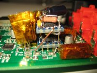
The Kapton tape mess is the 15x 1uF ECPU caps in parallel per output of the ES9018K2M and then another 10x per output of the OPA1612.
I don't have any equipment to make measurements, but it worked and didn't add any audible noise, which is a win as far as I'm concerned. Can't be any worse than the X7R caps that the virtual ground replaced.
The Kapton tape mess is the 15x 1uF ECPU caps in parallel per output of the ES9018K2M and then another 10x per output of the OPA1612.
Attachments
I'm guessing something like this...Sounds very interesting! Would you mind giving us a reference?
https://www.ebay.com/itm/254327406170
Yes, the module I posted takes a 10-16V input and has dual 12V outputs which can be wired for a symmetrical supply.

Sorry, been busy all day!Sounds very interesting! Would you mind giving us a reference?
The ones I found were made by Traco Power. Here is one example. Six bucks Canadian, accepts 12 Vdc input, spits out plus/minus 15 volts DC at up to 2 watts: https://www.digikey.ca/en/products/detail/traco-power/TBA-2-1223/9698342
There are other members in the family that will spit out +/- 15V from a 5V DC input (think surplus USB charger). And still others that spit out +/- 12 volts instead of +/- 15 volts. And others that are limited to 1 watt output power, or go up to 3 watts.
These are switching regulators, with switching frequency in the range of 70 kHz to 150 kHz, so some care will have to be taken in layout and shielding to make sure you don't have 70 kHz noise added to the op-amp audio output.
I have been looking for something like these for a long time. Until recently, I couldn't find it, except at much higher prices.
-Gnobuddy
I used some 3W 5V to +/-15V DC to DC converters and hand wound common mode chokes to clean up the output - DC was pretty clean but the converter radiated 70kHz all over the inside of the enclosure - lots of shielding helped but did not eliminate the problem. Were it me I would use linear +/-15V regulators and a small transformer.
Look for Elvee's denoizator circuit here: https://www.diyaudio.com/community/...-retrofit-upgrade-any-317-based-v-reg.331491/
Also see http://www.wenzel.com/documents/finesse.html
Works well with the LM337 as well.
If you are build a DAC and pushing the limits of what you can accomplish why start with a big compromise? 😀
Didn't know this one 😎I used some 3W 5V to +/-15V DC to DC converters and hand wound common mode chokes to clean up the output - DC was pretty clean but the converter radiated 70kHz all over the inside of the enclosure - lots of shielding helped but did not eliminate the problem. Were it me I would use linear +/-15V regulators and a small transformer.
Look for Elvee's denoizator circuit here: https://www.diyaudio.com/community/...-retrofit-upgrade-any-317-based-v-reg.331491/
Also see http://www.wenzel.com/documents/finesse.html
Works well with the LM337 as well.
If you are build a DAC and pushing the limits of what you can accomplish why start with a big compromise? 😀
I got really lucky years ago and bought a bunch of +/-15V 10W isolated DC-DC converters on ebay for $10 each. I've uses quite a few in projects like headphone amps and still have half a dozen or so. Cost prohibitive to use at full price...
https://www.mouser.com/ProductDetai...WR-15-330-D12A-C/?qs=b13bmSh8y6xAobPTcN9SYQ==
https://www.mouser.com/ProductDetai...WR-15-330-D12A-C/?qs=b13bmSh8y6xAobPTcN9SYQ==
I think haglabs has a design (see bugle2) that uses the rail splitter to get +-12V from 24V input.
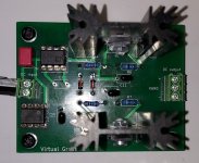
I really hate debugging these circuits... 🤢 But it helps if you solder the transistors with the correct orientation... 😱
Nevertheless, this circuit works quite well using the OP77. Will do measurements later.
But, as expected, you may need good heatsinks 😉
Nevertheless, this circuit works quite well using the OP77. Will do measurements later.
But, as expected, you may need good heatsinks 😉
Attachments
- Home
- Amplifiers
- Power Supplies
- Virtual Ground Circuit: Which OpAmp to Choose?