thank you, in reference to my question i only asked because both c gnd and r gnd appear to be both black in color but perhaps thats from being burnt /fried though. you might be right in them both being resistors but its extremely hard to tell if the black is just old burnt tan color or notNot always. Resistors typically have markings giving the value and ceramic capacitors (often pink or beige) generally have no markings. Resistors in blue are shown below.
It's virtually impossible for a resistor and a capacitor to burn identically, as these have. They have completely different structures.
so from said statement you are thinking they are both resistors then? evidence would support as they seem both burnt black color and identical structure, if i am correct i believe a smd tan capacitor is almost a little thicker than the smd black resistorsIt's virtually impossible for a resistor and a capacitor to burn identically, as these have. They have completely different structures.
c-grnd and r-grnd chips are identical in size.
from this assumption i am making i will also order the capacitor smds just in case. ordering these plus the panasonic capacitor you linked me in page 1 to order.That's a (somewhat) educated guess.
1K Ohm Resistors SMD 0805 0.1W 1% P1.00KCTR ERJ6ENF1001V Metal Glaze
Ceramic Capacitor 100nF .1uF 50V X7R 0805 10% SMD AVX 08055C104KAT2A (hoping 10% isnt too wide of tolerance)
last question before i order, concerning the panasonic 10uf 250v film capacitors, ive been doing some reading and wondering if i should install this instead? https://www.ebay.com/itm/284005120206?hash=item42200638ce:g:QngAAOSwla9fV-Xs a high end audio crossover capacitor for roughly the same price
would it sound better than the film capacitor since its marketed as a "high end audio crossover capacitor"?
would it sound better than the film capacitor since its marketed as a "high end audio crossover capacitor"?
For the most part, special audio capacitors are nothing special. Some have higher tolerances but I put no faith in them being better.
This is a film cap as was the one I suggested. That said, the information for the cap goes from 2.0uF to 10uF so I can't really trust anything on the page.
I've never tried the one above but I've used a lot of the ones I suggested and have never had one fail.
This is a film cap as was the one I suggested. That said, the information for the cap goes from 2.0uF to 10uF so I can't really trust anything on the page.
I've never tried the one above but I've used a lot of the ones I suggested and have never had one fail.
i was not worried about it failing, more so how it might sound; just wondering if it is worth the upgrade or there are dayton ones that have tolerances of 1%For the most part, special audio capacitors are nothing special. Some have higher tolerances but I put no faith in them being better.
This is a film cap as was the one I suggested. That said, the information for the cap goes from 2.0uF to 10uF so I can't really trust anything on the page.
I've never tried the one above but I've used a lot of the ones I suggested and have never had one fail.
i did a bit of research (not that i know what im doing really, just randomly googling things)
and i came across a very interesting read perhaps some people here on a hours free time might be interested to check out the testing these guys did with different capacitors and replacing components and resistances, apparently i learned an electrolyte capacitor has 5x the resistance or takes 5 times as longer than a film capacitor, interesting! copy and pasted from another forum below
perhaps this makes more sense to you but theres a massive amount of research they did on this and charts.
very interesting
https://www.audiosciencereview.com/...rade-in-crossover-is-it-audible-part-2.12447/
Hi, so you are saying there is no difference between expensive and cheaper capacitors.
There are clearly measurable differences, so the resistive part of the electrolytic capacitor (very cheap) is up to three times as high as that of the film capacitor (more expensive) in my examples.
However, the effects of these measurable differences hardly make a measurable "acoustic" difference when used in the crossover of loudspeakers.
The impulse response, the frequency response and the IMD change only minimally (hardly measurable) in the application range of the capacitors - that is for large capacitances (>80µF) in the bass/midrange and capacitances <20µF in the high frequency range.
When moving from the low kHz range to the MHz range, the differences can be dramatic, but this is irrelevant for LS crossover.
The "acoustically" measurable changes caused by possible component tolerances (mostly at +-5% or +-10%, rarely +-2%), on the other hand, are significantly higher and can be so large that audible differences can occur when capacitors are replaced - for more detail see part one, section"2) Capacitors - low capacitance deviations"" "
i guess my question is just, if i get a tighter tolerance i would get a better sound? as they are claiming in this last sentence above
What was the tolerance of the capacitor that was in it originally? Electrolytics can be ±20%.
I'm going to say that the ebay caps will not do any better than the ones I recommended. If there are those who disagree, they should say so.
This capacitor is bypassing the 80kHz-150kHz carrier that would have made it through the inductor. No audio actually passes through it. Depending on the feedback circuit for the amp, you could half or double the value of the capacitor and you would see no difference in the output.
thank you for explaining in depth. i have no idea the tolerance of the old blown cap. it never gave a tolerance value marking on itWhat was the tolerance of the capacitor that was in it originally? Electrolytics can be ±20%.
I'm going to say that the ebay caps will not do any better than the ones I recommended. If there are those who disagree, they should say so.
This capacitor is bypassing the 80kHz-150kHz carrier that would have made it through the inductor. No audio actually passes through it. Depending on the feedback circuit for the amp, you could half or double the value of the capacitor and you would see no difference in the output.
i assume as long as i stay within a 10% tolerance range i should be finethank you for explaining in depth. i have no idea the tolerance of the old blown cap. it never gave a tolerance value marking on it
im going to order the panasonic one you suggested from mouser, it seems 10uf 250v is EXTREMELY hard to find in radial terminal style. i just dislike the fact that mouser shipping ups ground is the same price as ups 2nd day. like how does that even make sense, capitalizing on shipping lolYes, 10% with a good quality capacitor. What have you decided to use?
ordered. i will report back when i installed all the necessary components and fire her up. I assume friday will probably be go-time.
i am considering installing 2 smd 1k resistors where c-gnd and r-gnd are first, if that fails me, i suppose i can then install the 1k resistor and .1uf cap next
Do you think that would be a good idea ?
Last edited:
VERY IMPORTANT GAME CHANGER INFO please read perry!
so im an idiot, i didnt notice there were 2 separate sets of RCAs on this board, the other set was master slave, i was measuring the master slave to secondary CT,
so redoing the measuring the REAL numbers for RCA shielding to secondary CT and negative speaker terminals,
right side all reads 26 on 200k ohms to both secondary ct and neg speaker terminals both sides
left side rca reads all 58 on 200k ohms to both secondary ct and neg speaker terminals both sides
all numbers are steady, no fluctuation
does this change the possibly percieved setup now of Cgnd and Rgnd?
i apologize for not catching this sooner and being new to this.
i also contacted maxxsonics support for cgnd and rgnd values on this board, fingers crossed for a reply
What do you measure across the R-gnd pads right now? I assume that the R-gnd and C-gnd are open.
Are you 100% sure that you have it right with this second set of readings? They'd be more of what I'd expect on the master/slave jacks.
Are you 100% sure that you have it right with this second set of readings? They'd be more of what I'd expect on the master/slave jacks.
i was wrong, i put the sides of the amp back together to make sure to not get switched up, we were originally right, i measured the slave master jack today, the amp is a little confusing becauuse the RCAS are identical opposite sides clearanceWhat do you measure across the R-gnd pads right now? I assume that the R-gnd and C-gnd are open.
Are you 100% sure that you have it right with this second set of readings? They'd be more of what I'd expect on the master/slave jacks.
so everything is okay the first time we did it, i messed up today. wish i could edit or delete the post above now.
BOTH C-gnd and R-gnd on 200k ohms reads 15/19 but only for traces of a second i did multiple readings, 15 and 19 are the only numbers on both that seem to come up for fractions of a second which an educated guess i assume they are the same then and one is not a .1uf capacitor? but thus they are both resistor SMDs? as for the values i have no idea.
just received the panasonic caps today, should expect the resistors tmrw and will report back once installed.
They are resistors being used sort of like a fuse I think. The markings are 0. Hope this helps.Thank you!!! They are fried just looking at both tiny resistors, do you know what proper replacement i can order for both Cgnd and Rgnd? thank you
Attachments
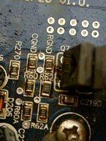
they are marked 0 wow that doesnt help lol. are you able to measure with a multimeter any chanceThey are resistors being used sort of like a fuse I think. The markings are 0. Hope this helps.
- Home
- General Interest
- Car Audio
- perry babin i need your help! hifonics brutus bxx4000.1d blown capacitors, replaced, still in protect. guessing driver board ?