200 ohms setting, all 4 secondary CTs to both (-) speaker terminals read 3-4Secondary CT to speaker negative?
Were any RCAs plugged into the amp when you measured the resistance between the two RCA shields?
noWere any RCAs plugged into the amp when you measured the resistance between the two RCA shields?
There are at least two types of input circuits on this general type of amp.
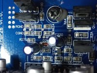
The most common has the RCA shield connected to the secondary ground (and negative speaker terminal). This type often has a 1k resistor for R-gnd and a 0.1uF capacitor for C-gnd.
Another type has a noise cancelling input and no direct connection between the RCA shields and the secondary ground. I've seen this type with a 1k resistor or a jumper wire for R-gnd. The C-gnd component can be omitted or a 0.1uF capacitor (which is useless with the parallel jumper wire).
I think it would be safe to use a 1k resistor for R-gnd but I can't be 100% sure because the RCA shields reading so low of a resistance doesn't really look like the noise cancelling input.
thank you, does it matter what voltage and wattage i find? would these work for r-gnd? https://www.amazon.com/1k-ohm-Resistor-Resistors-Tolerance/dp/B07DHGV4BT
and this https://www.amazon.com/20pcs-Cerami...l&sprefix=1uf+capacitor,industrial,79&sr=1-14 for the capacitor?
and this https://www.amazon.com/20pcs-Cerami...l&sprefix=1uf+capacitor,industrial,79&sr=1-14 for the capacitor?
Last edited:
A lot of the board layouts are copy and paste. The C-gnd is typically a capacitor but in this amp the components for both C and R-gnd may both be resistors.
is there a way we can measure this or tell, even if c grnd and r grnd are fried? should i try to contact maxxsonics for the schematic?A lot of the board layouts are copy and paste. The C-gnd is typically a capacitor but in this amp the components for both C and R-gnd may both be resistors.
If you can get the value or diagram, that would be great but manufacturers, with few exceptions, are not very helpful.
Remove them from their pads and see if you get any readings across them.
Remove them from their pads and see if you get any readings across them.
will do tomorrow and report back, thank youIf you can get the value or diagram, that would be great but manufacturers, with few exceptions, are not very helpful.
Remove them from their pads and see if you get any readings across them.
took off c gnd and r gnd, tried to get any readings with a multimeter and on any setting nothing comes up at all.If you can get the value or diagram, that would be great but manufacturers, with few exceptions, are not very helpful.
Remove them from their pads and see if you get any readings across them.
i then proceeded to put the 2 chips under a 15x microscope and well... the numbers are completely fried and burned i cant tell anything except a shiny metallic surface ontop.
are other tricks in the book we can try to decipher these chip ratings?
I don't know of any other way.
I'd install 1k worth of resistance, assemble the amp and test with a 20 amp fuse in the B+ line to see if any problems show up in the vehicle with the engine running (to check for noise).
I'd install 1k worth of resistance, assemble the amp and test with a 20 amp fuse in the B+ line to see if any problems show up in the vehicle with the engine running (to check for noise).
would this spec be appropriate to replace the C and R gndI don't know of any other way.
I'd install 1k worth of resistance, assemble the amp and test with a 20 amp fuse in the B+ line to see if any problems show up in the vehicle with the engine running (to check for noise)
- 1k ohm - 1/8 Watt 0805 SMD Resistor Resistors 5% Tolerance (Ships from US)
- Resistance: 1k ohm
Last edited:
i would assume to just get the highest voltage rating i can find? 50v or something as long as the .1uf matches up and i go overkill on the voltage spec i should be good yes?would this spec be appropriate to replace the C and R gnd
last question, what voltage would i need?
- 1k ohm - 1/8 Watt 0805 SMD Resistor Resistors 5% Tolerance (Ships from US)
- Resistance: 1k ohm
Yes on the resistor if the size matches.
On the capacitor, 50v would be OK. Typically, there would never be more than a fraction of a volt across these two components.
On the capacitor, 50v would be OK. Typically, there would never be more than a fraction of a volt across these two components.
random question, i keep coming across smd capacitors and all the capacitors look tan on top, all the resistors seem to look black ontop. is this true for all smd components (caps , resistors)?Yes on the resistor if the size matches.
On the capacitor, 50v would be OK. Typically, there would never be more than a fraction of a volt across these two components.

- Home
- General Interest
- Car Audio
- perry babin i need your help! hifonics brutus bxx4000.1d blown capacitors, replaced, still in protect. guessing driver board ?