This relates to the renovation of a vintage 1940/50's PA amp with an 807 PP fixed bias output stage that included a rarely seen PP grid choke. The original amp didn't include feedback but I am aiming for a 'presonance' control that will need some frequency management of feedback to ensure stability, even though feedback level is circa 6dB max.
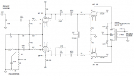
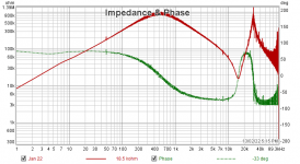
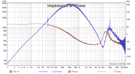
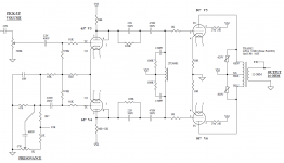
A draft schematic of the modified PI and output stages is shown below. The 2TU6981 PP grid choke provides a high impedance load to the PI stage without having to use relatively low valued grid leak resistors (ie. 100k). Each choke half has a high primary inductance of circa 600H at 40Hz, but also a 16kHz resonance from a circa 200pF winding shunt capacitance and a few hundred mH leakage inductance, followed by another resonance at 30kHz, as indicated by the impedance plot shown below. The choke inductance needed some modified PI stage output coupling cap management at the low frequency end otherwise it causes an LC related response peak with the PI stage output coupling cap at what was a noticeable 40-50Hz.
The renovation is nearly complete and the amp happily provides 40W clean in to a resistive load, and about 70W cranked. So now to the application of feedback for the presonance effect. The OPT is nicely interleaved so I am not expecting significant resonance effects from that aspect, and can include some HF phase compensation (across feedback resistor and using some series output inductance) if needed for such a low level of feedback. I need to add in a dominant open-loop HF filter which will be a capacitor across the PI stage anodes, but will get to that once I have the grid choke under control.
So back to the grid choke and how to tame its behaviour. I've just confirmed that there is a dominant 16kHz ringing on a low frequency squarewave signal through the amp. My initial guess is to shunt each choke half-winding with an RC to apply something like a 100kohm dampening above 10-15kHz, as that seems the simplest way forward. Happy to hear of any other options to try and mollify the resonance effects of this grid choke (apart from ditching it 🙄). I should get to this on the bench in the next few days to see how much influence the RC can be, and how much HF roll-off I need for feedback stability.
Tim
Attachments
Well you picked an easy one. Buck up!
But really, resonances are two pole; tough customers in what's ideally a single pole world.
Gotta ask, how married are you to this scheme? Are modern schemes with feedback taken from the OPT primaries, etc. open for consideration? Otherwise, the classic long-loop feedback schemes are a hard slog if the complications of the high intrinsic output (source) impedance to an actual real-world complex load are included.
Of course you know all this. You're possibly trying to raise the quality of discourse, and it's greatly appreciated.
Chris
Pretty much every vintage restoration I do has something interesting show up - and this amp was no exception. The grid choke has been intriguing - so far I haven't come across a similar deployment or an academic or magazine reference of such a PP operation. So its got to stay in the amp no matter how 👽 or compromising it becomes. And it is the journey that enthuses me - so whether the presonance control works out is just icing on the cake.
Normally an output stage resonance is embedded in the OPT, and I guess there could be particularly bad PP OPT's that have such a very low first resonance, but this one is notably low in frequency - so not the normal hi-fi part to apply stability management techniques to.
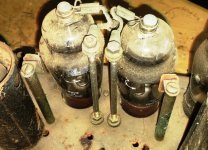
This model of PA amp was made by AWA, a large manufacturer. Somewhat surprisingly the first batch of this amp used 6L6G and the amp was rated at 35W. My serial number comes from a later batch and they had by then changed to a pair of 807's. But to fit the 807's in the chassis/top cover they recessed the valve bases, and put a somewhat diy metal cover over the top (cover is not shown in photo below but the two rear mounting tabs are), and used an insulated pair of rods to pass the anode connections from under the chassis to the top caps - whew! We are guessing the bean-counters knew that 807's were just so cheap and plentiful after WW2 that even with all the hardware mods, the final amp was still cheaper to build.
Normally an output stage resonance is embedded in the OPT, and I guess there could be particularly bad PP OPT's that have such a very low first resonance, but this one is notably low in frequency - so not the normal hi-fi part to apply stability management techniques to.
This model of PA amp was made by AWA, a large manufacturer. Somewhat surprisingly the first batch of this amp used 6L6G and the amp was rated at 35W. My serial number comes from a later batch and they had by then changed to a pair of 807's. But to fit the 807's in the chassis/top cover they recessed the valve bases, and put a somewhat diy metal cover over the top (cover is not shown in photo below but the two rear mounting tabs are), and used an insulated pair of rods to pass the anode connections from under the chassis to the top caps - whew! We are guessing the bean-counters knew that 807's were just so cheap and plentiful after WW2 that even with all the hardware mods, the final amp was still cheaper to build.
Attachments
AWA has such a magical pre-war Radiotron ring to it. Wish I could help, but you're into four poles (minimum) and a critical load dependence. My only possible thoughts are to try to make things into manageable single poles (brute force, of course), which isn't helpful. Zobels?
Is this from South Park? : "If your only tool is a hammer, every problem looks like a hippie".
All good fortune,
Chris
Is this from South Park? : "If your only tool is a hammer, every problem looks like a hippie".
All good fortune,
Chris
Last edited:
A local Fdbk approach would seem the simplest brute force approach.
But if you want to tangle with the xfmr "demons" inside, you could try positive current Fdbks from the output tubes cathodes ( low value current sense resistors with an attenuator) back to the driver cathodes WITH some series resonant LC traps in line with them. (same freq. as xfmr resonance). Fdbk levels adjusted to give enough boost to flatten the original resonance. The phase of the pos. Fdbks would then adjust in phase automatically on either side of the xfmr resonance. One could tailor the comps. width with a high value resistor across the traps, but too low an R here would begin to remove OT primary R as well (neg. resistance effect), likely making resonance matters worse (sharper resonance).
But if you want to tangle with the xfmr "demons" inside, you could try positive current Fdbks from the output tubes cathodes ( low value current sense resistors with an attenuator) back to the driver cathodes WITH some series resonant LC traps in line with them. (same freq. as xfmr resonance). Fdbk levels adjusted to give enough boost to flatten the original resonance. The phase of the pos. Fdbks would then adjust in phase automatically on either side of the xfmr resonance. One could tailor the comps. width with a high value resistor across the traps, but too low an R here would begin to remove OT primary R as well (neg. resistance effect), likely making resonance matters worse (sharper resonance).
Last edited:
For initial measurement simplicity I'll re-do the choke half-winding impedance plot but with a shunt RC on each half. and do some forward path gain frequency plots without feedback (with and without shunt RC, and with and without a PI output shunt C) to get a better view of the likely level of feedback that could be applied before encroaching on instability conditions due to the presonance control. That should keep me busy for awhile.
My building partner, iain42, is tackling something similar currently. He'd built a pair of replica Brooks (model 10s ?) using custom wound supposed replica chokes and OPTs, and had plenty of stability issues. Disappointed, he's gutted them for a new attempt, reusing the existing iron, power supplies, valves (mostly), etc. But he has the luxury of an extra gain stage. Would an extra stage fall within your game rules?
We're going to have a differential input stage of 6SL7 RC coupled to push-pull 6SN7 cathode followers with the choke in the 6SN7's cathodes to ground, and some small resistance to bring the total R up to 1K Ohm to bias the 6SN7s. Grids of the 2A3 output valves are then direct coupled to the 6SN7 cathodes; individual output valve cathode bias resistors and bypass caps, etc. This scheme is to keep the choke at as low as possible a circuit impedance (brute force), but also a low DC resistance to ground for the ancient 2A3s' grid current. It does require one more gain stage than you currently have.....
All good fortune,
Chris
My vintage amp has two sequential preamp gain stages using 6J7's. The input stage is pentode and circuitry has been adjusted to dumb down the gain as much as practical (x63 mid-band). The second stage is triode connected and nearly x20 gain. As it is for a guitar amp application there is plenty of open-loop gain to wash off, given the PI gain is circa x6, so 2 front panel pots allow the preamp stage output levels to be adjusted to suit.
I must admit that being able to easily measure part impedance up to 100kHz can identify some unexpected ills and differences. I recently went through a batch of testing on my vintage collection of Williamson output transformers, and differences were easily identified - and sometimes not in-line with what the contemporary adverts were saying.
I must admit that being able to easily measure part impedance up to 100kHz can identify some unexpected ills and differences. I recently went through a batch of testing on my vintage collection of Williamson output transformers, and differences were easily identified - and sometimes not in-line with what the contemporary adverts were saying.
They musta got a Special Deal. Maybe the currents of war left an eddy of 807 downunder. I have my finger in 1949 just now and prices are real darn similar. More variation between dealers than between type numbers.807's were just so cheap and plentiful after WW2
I would put <50k across each half of the winding, to spoil the Q. To avoid loading the midband maybe 200pFd in series.
Attachments
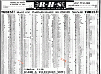
I'm pretty sure AWA was very linked to many Aussie defence contracts, so plausible that they had quite a stock of 807's to call on. Our local RTV&H magazine isn't too flush with valve price comparisons - in 1947 the 807 was 16/6, and a 1954 advert had 807 at 20 to 25/- (shilling) but sadly no 6L6 price comparisons.
I just tried 100k+82pF and 100k+150pF as shunt RC's across each half of the grid choke. The R certainly dampens the original 30kHz resonance and has some effect on the original 16kHz, with the resonance frequencies lowered from the added C. An RC is certainly easy to add/tweak so for now I'll turn to looking at the open loop response of the PI and output stage (I'll bypass the two preamp stages to simplify interpreting the responses).
I just tried 100k+82pF and 100k+150pF as shunt RC's across each half of the grid choke. The R certainly dampens the original 30kHz resonance and has some effect on the original 16kHz, with the resonance frequencies lowered from the added C. An RC is certainly easy to add/tweak so for now I'll turn to looking at the open loop response of the PI and output stage (I'll bypass the two preamp stages to simplify interpreting the responses).
Attachments
Your honor, the defendant ADMITS to having available octal sockets. The prosecution rests.My vintage amp has two sequential preamp gain stages using 6J7's.
I must admit
Always the best fortune,
Chris
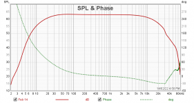
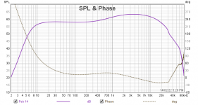
Quick progress. With no feedback, the frequency response of the PI and output stage at 1W is shown in the attached "1G7053 16ohm 1W spectrum PI input baseline.png".
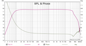
The other three plots are with the presonance circuitry fitted and a nominal 6dB of feedback (updated schematic - plots indicate circa 5dB but I nudged a pot). The presonance pot provides about 5dB treble boost in full CW position, and about 5dB of treble cut in CCW position. The 30kHz resonance of the grid choke shows through when treble is suppressed by more feedback in CCW position. That 30kHz resonance is mollified by 2dB when the 100k/82pF RC networks are added, but the resonance is not overtly significant.
I'm thinking my initial testing that showed up a strong 16kHz resonance had a bad connection somewhere - doh. Anyway I still need to check for stability across a broad range of loads to see if that resonance flares up, and check if the treble/cut frequency corner is ok.
Attachments
-
 AWA IG7053 modified draft schematic.PNG32.3 KB · Views: 74
 -
 1G7053 16ohm 1W spectrum PI input baseline.png15 KB · Views: 71
 -
 1G7053 16ohm 1W spectrum PI input presonance full CCW.png15.1 KB · Views: 63
 -
 1G7053 16ohm 1W spectrum PI input presonance mid.png14.4 KB · Views: 61
 -
 1G7053 16ohm 1W spectrum PI input presonance full CW.png15.4 KB · Views: 63
Price for New, just manufactured tubes must have been similar, basically same guts and materials so same or close production price.They musta got a Special Deal. Maybe the currents of war left an eddy of 807 downunder. I have my finger in 1949 just now and prices are real darn similar. More variation between dealers than between type numbers.
BUT there was A TON of surplus military tubes around, bought by lot at Government Auction for peanuts , then resold.
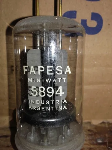
When I started making amps in 1969, 6L6 were hard to find in Argentina and VERY expensive, besides we are an "European" Country, not a US type, so 6L6 was almost unused, 6V6 completely unknown , popular tubes were EL34 and EL84, of which we even had a local Factory (Philips=FAPESA) so no big deal.
While I could buy NIB 807, military surplus, for a very low price.
A Fapesa-Philips-Miniwatt tube, locally made:
It is synergistic. The max-power condition for 6L6/807 is AB2, grid current. Straight R-C coupling would de-bias when grid current started (unless Rg is <1K). The choke allows faster re-bias to nominal condition. And doubles the available current since one side helps the other over the peak.grid choke provides a high impedance load to the PI stage without having to use relatively low valued grid leak resistors
Bogen had an amp. But Bogen had so many amps! It was choke-coupled cathode-followers, probably better linearity and coil-damping. IIRC Brooks went down this trail too?
First you take a pair of pentodes/beam power tubes in push pull (not UL mode, and not Triode wired mode).
The output transformer has primary inductance, primary distributed capacitance, primary to secondary capacitance, 1/2 primary to the other 1/2 primary leakage inductance, and primary to secondary leakage inductance.
Then you use the very high plate impedances to drive the 'resonator' . . . Oh, excuse me, that output transformer.
Then, you apply some global negative feedback around that output transformer, the output tubes, driver stage, and perhaps the input stage too.
Resistor load on the secondary is one thing, but getting all that stabilized when running another set of resonators (loudspeakers), can be a challenging project.
Is it any wonder that some designers choose to use UL negative feedback, Schade negative feedback, plate to driver cathode negative feedback, Triode wired pentode/beam power tubes, or Triodes . . . in order to get the output stage's plate impedance lower (lower plate impedance before applying any global negative feedback that comes from the secondary of the output transformer)?
And then, add a presonance gain / phase shift network to all that.
I am to lazy to try and compensate a pentode/beam power stage that uses global negative feedback from the output transformer secondary. I do admit that.
Last edited:
- Home
- Amplifiers
- Tubes / Valves
- Options to mollify a 16kHz resonance in a PP output stage