Hi, has anyone got one of these? It's the phono stage from the Marantz model 7... or so the ad says. Comments? Experience?
Thanks!
(edit Feb 10 - added schematic provided by vendor)
Thanks!
(edit Feb 10 - added schematic provided by vendor)
Attachments
Last edited:
I can highly recommend the EAR834 clone "black board" version. I've built a half a dozen of these just as they come (upgraded a few things like the coupling caps) , and everyone I have sold a finished preamp built around them loves it! Oh and I love mine too 🙂


I can highly recommend the EAR834 clone "black board" version. I've built a half a dozen of these just as they come (upgraded a few things like the coupling caps) , and everyone I have sold a finished preamp built around them loves it! Oh and I love mine too 🙂
View attachment 1023234 View attachment 1023235
That's the Zhili Audio version right?
jeff
I ordered an EAR834 clone board and got the one the OP has.
With half decent tubes in it, it works quite well.
I seem to recall that the EAR834 is very similar to the Marantz 7 circuit.
With half decent tubes in it, it works quite well.
I seem to recall that the EAR834 is very similar to the Marantz 7 circuit.
Yeah it is. With 7025 tubes, sounds really sweet.That's the Zhili Audio version right?
jeff
I can ditto this. I have built one of these boards and added some films in the power supply and used some really nice caps for signal and it's a great sounding phono preamp. You certainly can't buy anything in consumer product land for the same $ that would even come close...I can highly recommend the EAR834 clone "black board" version. I've built a half a dozen of these just as they come (upgraded a few things like the coupling caps) , and everyone I have sold a finished preamp built around them loves it! Oh and I love mine too 🙂
View attachment 1023234 View attachment 1023235
I compared it to a highly rated solid state phono-pre that cost close to $800 and this DIY tube kit sounds better.I can ditto this. I have built one of these boards and added some films in the power supply and used some really nice caps for signal and it's a great sounding phono preamp. You certainly can't buy anything in consumer product land for the same $ that would even come close...
I got a schematic for the ersatz Model 7 and added it to the first post.
I actually have one of these, and it doesn't work - motorboats. I'm looking at that HV series pass device with suspicion - a 2SK2700. I thought this was long obsolete?
I actually have one of these, and it doesn't work - motorboats. I'm looking at that HV series pass device with suspicion - a 2SK2700. I thought this was long obsolete?
So obsolete is often used for no longer made, it doesn't necessarily imply there is any issue with the part. And the 2SK117 is a long obsolete part that you can get out of China (and in lots of stuff from China like these boards) all day, every day with 0 issue. So that doesn't immediately make it suspect.I got a schematic for the ersatz Model 7 and added it to the first post.
I actually have one of these, and it doesn't work - motorboats. I'm looking at that HV series pass device with suspicion - a 2SK2700. I thought this was long obsolete?
First, are you sure its motorboating or is it just 60Hz hum? Did you buy the board complete or build it? My guess is if it's your build, something isn't in the right spot or connections were made that shouldn't have been. Also, just to rule it out, have you tried a different set of tubes?
As for test equipment, what do you have? Just a meter? Or do you have a scope?
Thanks all. I've verified the schematic is accurate. PCB layout added to first post.
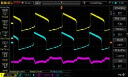
Here is a screenshot of mine. It is calm when running with an open input but motorboats when the input is terminated with a 1K resistor to simulate a phono cartridge.
Upper 2 traces are the outputs banging away at 6Hz and 100Vp-p(!). Lower trace is B+ rail ripple. The HV reg is working normally.
Here is a screenshot of mine. It is calm when running with an open input but motorboats when the input is terminated with a 1K resistor to simulate a phono cartridge.
Upper 2 traces are the outputs banging away at 6Hz and 100Vp-p(!). Lower trace is B+ rail ripple. The HV reg is working normally.
Attachments
So obsolete is often used for no longer made, it doesn't necessarily imply there is any issue with the part. And the 2SK117 is a long obsolete part that you can get out of China (and in lots of stuff from China like these boards) all day, every day with 0 issue. So that doesn't immediately make it suspect.
Long obsolete part + China? Guaranteed fake. Literally everything you see on eBay and AliExpress is re-marked. Those 50 cent AD797s that sell by the thousands? Proven fakes by a member here.
Filament regulator is also working normally. Here are the DC values when warm - the filaments are biased positive by that tap off the B+ supply.
B+ 270DC, ~30mVac
Fil voltage 12.55DC, <1mVac
Fil string bottom (pin 4) +80.7DC, <1mVac
Fil string top (pin 5) +93.3DC, <1mVac
B+ 270DC, ~30mVac
Fil voltage 12.55DC, <1mVac
Fil string bottom (pin 4) +80.7DC, <1mVac
Fil string top (pin 5) +93.3DC, <1mVac
The link will be no good in a week, look for the long black board and it has "Zhili Audio" printed on it.Can someone post a link to the correct EAR board to purchase
thanks
Well of course they are not original manufacture. That was implied, I guess I should be explicit. Since they are pennies I'm pretty sure no one is pulling a scam like possibly selling fake $20 opamps. And despite the swindlers out there, most of the good folk in China are out to make good products and make an honest living like the rest of us. I used to live there, it's true. Are we going to start labeling all Chinese and Russian tubes fakes now too? 😉 The other option, is we don't have any options, which doesn't sound better to me...Long obsolete part + China? Guaranteed fake. Literally everything you see on eBay and AliExpress is re-marked. Those 50 cent AD797s that sell by the thousands? Proven fakes by a member here.
Can someone post a link to the correct EAR board to purchase
thanks
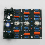
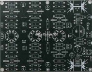
On the board, there are a few 384 clones... I have the Zhili Audio one as well, which is what I was commenting on, as is pictured here from an ebay ad. Note, it's a breakaway board, you can build it as one board or split the power supply off and move it away or even to a separate enclosure. Also, as you can see, it's available already assembled if you want to just swap just a few parts vs assemble it all.
So, just a thought, what happens if you don't simulate and actually just plug in a turntable? 2 reasons... it may just work, also, it would be nice to know that feedback loop is working correctly and didn't get an improper value stuffed in there. With regulation, I would think the 10uf PS caps are enough, but you could have a bad one...Here is a screenshot of mine. It is calm when running with an open input but motorboats when the input is terminated with a 1K resistor to simulate a phono cartridge.
Mmm, IMO all stuff bought via cheap online stores from China is suspect. And yes there IS choice. One can also buy NOS/NIB (from EU/USA) produced stuff that performs better and lives longer.
I would caution against buying a prebuilt board. I've bought 2 of them as "Kits" that included all the parts, and about 20% of the resistors were WAY out of spec. I'm pretty sure they would have just soldered them in place as they populated the board with these way out of spec resistors, they just didn't solder them in. A circuits like this needs resistors at least close in value to perform correctly.Also, as you can see, it's available already assembled if you want to just swap just a few parts vs assemble it all.
- Home
- Amplifiers
- Tubes / Valves
- Let's talk about this 'Marantz Model 7' board on eBay