Hi All,
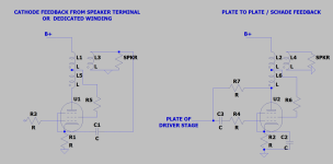
In the image below I present two kinds of local feedback typically seen on pentode output stages. I am currently using cathode feedback with great results, but the Schade Feedback intrigues me. What are the pros and cons of each method?
Many thanks,
Greg
In the image below I present two kinds of local feedback typically seen on pentode output stages. I am currently using cathode feedback with great results, but the Schade Feedback intrigues me. What are the pros and cons of each method?
Many thanks,
Greg
Attachments
Been doing some simulations.... With typical high gain input tubes with high plate resistance and running a few mA, Schade doesn't seem to have much current drive at high frequency for large output tubes. Would that be a correct observation?
Last edited:
Cathode feedback is series-applied voltage feedback. The other would be parallel-applied voltage feedback but I would quibble with calling it "Schade" because O. H. Schade used series-applied voltage feedback in his paper (using an interstage transformer).
Looking at series and parallel feedback in op-amps can be instructive as this is very similar.
As far as current drive goes, what makes you say that? What doesn't have current drive? I'm not following. It is current drive from the previous stage.
Looking at series and parallel feedback in op-amps can be instructive as this is very similar.
As far as current drive goes, what makes you say that? What doesn't have current drive? I'm not following. It is current drive from the previous stage.
You cannot separate either of these circuits from their driver stages. They both interact with them strongly.
Cathode feedback is series-applied voltage feedback. The other would be parallel-applied voltage feedback but I would quibble with calling it "Schade" because O. H. Schade used series-applied voltage feedback in his paper (using an interstage transformer).
Looking at series and parallel feedback in op-amps can be instructive as this is very similar.
As far as current drive goes, what makes you say that? What doesn't have current drive? I'm not following. It is current drive from the previous stage.
Thanks for the reply...I need to go do some reading.
Sorry I wasn't clear. What I meant was that if you have, say a 12AX7 input stage driving a KT88 output stage, all the various impedances with the parallel feedback method don't seem to allow the KT88 to be driven properly at high frequency. It's not a shortfall of the feedback method itself, more a problem with the implementation using common tubes without an intermediate driver stage.
Last edited:
Well, with parallel-applied feedback, the driver is working into a much more vertical load. You want to find a tube that will be most linear when operated that way. Pentodes tend to be a better choice.
I think you could come up with a tube combo that would do the job well. I did it once with a p-channel fet follower and a resistor-divider. See this blog post for more info.
I think you could come up with a tube combo that would do the job well. I did it once with a p-channel fet follower and a resistor-divider. See this blog post for more info.
I don't know who came up with the idea of using the cathode resistor to ground and a large capacitor to the secondary winding but it is not how it was done originally. A capacitor in series with an inductance gets a resonant circuit, a resistor across the capacitor stops instability of such resonant circuit.
https://www.vintage-radio.net/forum/showthread.php?s=4409fa7d95bd74a77024840a4046523d&t=182743
To get back to your question: A transformer introduces distortion, mainly H2. Cathode feedback minimizes the distortion but you have to use tubes that are high Gm (EL84 / EL34 / 7591) and not tubes that use high amounts of drive like the KTxx / 6L6 etc.
Schade feedback keeps the transformer out of the loop, some people like the sound of that in small amplifiers. You'll have to realise that 2% H2 distortion of 30 Hz being at 60 Hz sounds louder than the fundamental 30Hz.
And to get back to your thread about tube variability: Learn how to model load lines, your design is not running in the most linear part of the output tube. Here, I'm doing you a favour and do the work for you about the difference between class A and class AB: https://www.vtadiy.com/book/chapter-3-vacuum-tubes-as-amplifiers/3-5-amplifier-classes/ .
In the last picture on this page you can see how moving to a higher voltage would distort the symetry of the sinus. https://www.analogethos.com/post/load-lines
Attached a document on how to work with loadlines.
Attachments
I like plate to plate "Schade" feedback on the SE amps I have been building because it's fairly easy to tune looking at the distortion curve and also listening to the amp, as the value of this resistor changes the tone of the amp. Higher values sound brighter and lower values sound less bright. Works as a sort of tone control to voice the amp to your speakers/room.

Thanks SpreadSpectrum, I really like your p-follower design. I will keep experimenting with different driver stages and see if I can come up with one that I like.Well, with parallel-applied feedback, the driver is working into a much more vertical load. You want to find a tube that will be most linear when operated that way. Pentodes tend to be a better choice.
I think you could come up with a tube combo that would do the job well. I did it once with a p-channel fet follower and a resistor-divider. See this blog post for more info.
I like plate to plate "Schade" feedback on the SE amps I have been building because it's fairly easy to tune looking at the distortion curve and also listening to the amp, as the value of this resistor changes the tone of the amp. Higher values sound brighter and lower values sound less bright. Works as a sort of tone control to voice the amp to your speakers/room.
Thanks Stephe, this makes sense I suppose, more feedback with the lower values. I am going to have to give it a go. I think I do prefer the idea of plate to plate over cathode feedback.
I have noticed that some of your amps roll off pretty rapidly above 10kHz. Do you think this is the edcor output transformer or the high impedance/low current driver you are using - your 6SQ7/EL34 amp only runs a mA or two in the input stage?
Ah ok thanks EL506, that's very interesting.I don't know who came up with the idea of using the cathode resistor to ground and a large capacitor to the secondary winding but it is not how it was done originally. A capacitor in series with an inductance gets a resonant circuit, a resistor across the capacitor stops instability of such resonant circuit.
I blatantly lifted my output stage design from the Tubelab SSE here: http://tubelab.com/designs/tubelab-sse/schematic/
So something like this instead (using a triode for schematic simplicity)?
And to get back to your thread about tube variability: Learn how to model load lines, your design is not running in the most linear part of the output tube. Here, I'm doing you a favour and do the work for you about the difference between class A and class AB: https://www.vtadiy.com/book/chapter-3-vacuum-tubes-as-amplifiers/3-5-amplifier-classes/ .
In the last picture on this page you can see how moving to a higher voltage would distort the symetry of the sinus. https://www.analogethos.com/post/load-lines
Attached a document on how to work with loadlines.
Thanks for the aritcles and well written. I am quite familiar with load lines and finding the theoretical optimum operating point. However, any discussion on operating points seems to yield heaps of people who prefer higher operating voltages coupled with high OPT impedance, claiming that damping factor into real loads is equally important. I found the whole situation so ambigious and confusing that once again I based my B+ voltage and OPT impedance on the Tubelab SSE which seems to be a well regarded design.
PLease also note that my amp in the other thread is actually an EL34 amp and does not have enough current supply to power 2 KT88's at their best ratings. The thread was not about the absolute performance, more the relative performance between multiple new tubes from a single manufacturer.
Thank you all for your help!
Voltage sensing negative feedback applied in series with signal increases voltage drive required by the amount of feedback. Voltage sensing negative feedback applied in parallel with signal ("Schade") increases current required from the driver by the amount of feedback. Second Law is inviolate.
For most practical amps, the amount of feedback voltage available from the output transformer's secondary is so small compared to output stage signal voltage as to not really matter - maybe a coupla dB, tops. But can't hurt, free, no harm, no foul.
I think many folks tend to underestimate the burden that "Schade" feedback places on the driver stage. A useful way to estimate it is to think of it as if it were Miller capacitance - it works exactly the same way and for the same reason. It's otherwise elegant, thus attractive, but does need to be considered. And it's the only way to derive a voltage sensing negative feedback from a simple single-winding primary and to apply it over only one stage (RC coupling assumed).
Deriving the sensing voltage from the primary is good for transformer distortion mitigation and for stability, and places the feedback around the highest distortion stage, if all else is well designed. All good stuff, but places a burden on the driver stage (Second Law). Fortunately for us, that stage has very well defined job requirements, and can be made arbitrarily close to perfect, which is not true for output stages.
All good fortune,
Chris
It's more I honestly don't care much about what's going on after 10K. If there is a db or so, especially past 15K, not much music is up there and my ears are pretty dead past 12K anyway lol.Thanks Stephe, this makes sense I suppose, more feedback with the lower values. I am going to have to give it a go. I think I do prefer the idea of plate to plate over cathode feedback.
I have noticed that some of your amps roll off pretty rapidly above 10kHz. Do you think this is the edcor output transformer or the high impedance/low current driver you are using - your 6SQ7/EL34 amp only runs a mA or two in the input stage?
That entirely depends on the ratio of primary to secondary and what tube is used. I manage to get close to 8% winding turns in the secondary and together with UL it does very nicely, thank you very much. Quad II did not have UL and the # turns in the CFB was 10% of the total..For most practical amps, the amount of feedback voltage available from the output transformer's secondary is so small compared to output stage signal voltage as to not really matter - maybe a coupla dB, tops.
Originally vinyl records were designed to reproduce 50Hz to 10K.It's more I honestly don't care much about what's going on after 10K. If there is a db or so, especially past 15K, not much music is up there and my ears are pretty dead past 12K anyway lol.
This is what I was getting at, although I misinterpreted the mechanism.I think many folks tend to underestimate the burden that "Schade" feedback places on the driver stage. A useful way to estimate it is to think of it as if it were Miller capacitance - it works exactly the same way and for the same reason.
Haha fair enough, my ears are no better!It's more I honestly don't care much about what's going on after 10K. If there is a db or so, especially past 15K, not much music is up there and my ears are pretty dead past 12K anyway lol.
That entirely depends on the ratio of primary to secondary and what tube is used. I manage to get close to 8% winding turns in the secondary and together with UL it does very nicely, thank you very much. Quad II did not have UL and the # turns in the CFB was 10% of the total..
I have had good results with my 8 ohm tap. I reckon if you had a 16 ohm tap like many Hammonds it might be ideal.
There are transformers for multiple primary impedances that can work out having higher than 16 Ohm on the secondary. There are also transformers that have a 32 ohm secondary. If there is some space then you can always add more windings yourself, it does not need to be thick wire......
I have had good results with my 8 ohm tap. I reckon if you had a 16 ohm tap like many Hammonds it might be ideal.
The late Patrick Turner website ( www.turneraudio.com.au) is no longer up, he had all the detailed information required for making transformers. You may be able to still access it on the web archive. (archive.org )
I understand this is a technical forum but I basically just try different things until I start seeing more power + less distortion and then fine tune things by ear from there. I'm sure an electrical engineer would say things like my 6SQ7 amp is all messed up, but several other people have built it and are as amazed as I am how good it sounds. There is some nice mojo going on between that 6SQ7 and a EL34 UL output tube using shade feedback.Haha fair enough, my ears are no better!
Nothing wrong with your philosophy at all in my books Stephe! Just trying to learn a bit of the technical side of things while I pursue this hobby.I understand this is a technical forum but I basically just try different things until I start seeing more power + less distortion and then fine tune things by ear from there. I'm sure an electrical engineer would say things like my 6SQ7 amp is all messed up, but several other people have built it and are as amazed as I am how good it sounds. There is some nice mojo going on between that 6SQ7 and a EL34 UL output tube using shade feedback.
Thanks for the tip! And yes a copy of the website from a few years back is indeed on the archive site.There are transformers for multiple primary impedances that can work out having higher than 16 Ohm on the secondary. There are also transformers that have a 32 ohm secondary. If there is some space then you can always add more windings yourself, it does not need to be thick wire.
The late Patrick Turner website ( www.turneraudio.com.au) is no longer up, he had all the detailed information required for making transformers. You may be able to still access it on the web archive. (archive.org )
In your schematic the grid resistor of 249K is connected to the cathode, which would mean there's no bias. It should be connected to ground. If you want to also apply GNFB to the stage preceeding the power stage, the secondary should be grounded at the point where L3 and L2 connect, so not at the bottom of L2. The GNFB can than be taken from the bottom of L2.Thanks SpreadSpectrum, I really like your p-follower design. I will keep experimenting with different driver stages and see if I can come up with one that I like.
Thanks Stephe, this makes sense I suppose, more feedback with the lower values. I am going to have to give it a go. I think I do prefer the idea of plate to plate over cathode feedback.
I have noticed that some of your amps roll off pretty rapidly above 10kHz. Do you think this is the edcor output transformer or the high impedance/low current driver you are using - your 6SQ7/EL34 amp only runs a mA or two in the input stage?
Ah ok thanks EL506, that's very interesting.
I blatantly lifted my output stage design from the Tubelab SSE here: http://tubelab.com/designs/tubelab-sse/schematic/
So something like this instead (using a triode for schematic simplicity)?
View attachment 1022469
Thanks for the aritcles and well written. I am quite familiar with load lines and finding the theoretical optimum operating point. However, any discussion on operating points seems to yield heaps of people who prefer higher operating voltages coupled with high OPT impedance, claiming that damping factor into real loads is equally important. I found the whole situation so ambigious and confusing that once again I based my B+ voltage and OPT impedance on the Tubelab SSE which seems to be a well regarded design.
PLease also note that my amp in the other thread is actually an EL34 amp and does not have enough current supply to power 2 KT88's at their best ratings. The thread was not about the absolute performance, more the relative performance between multiple new tubes from a single manufacturer.
Thank you all for your help!
If I'm not mistaken, connecting the resistor of 249K to the other side of R4 and C1 would create cathode bias but would undo most of the cathode feedback.
Last edited:
Oops, you're right. I made the schematic in a hurry and missed that!In your schematic the grid resistor of 249K is connected to the cathode, which would mean there's no bias. It should be connected to ground.
Ah yes I can see how that would work. Not a bad way to linearise the output and input but keep the overall GFB factor a bit lower and maintain stability. Great suggestion!If you want to also apply GNFB to the stage preceeding the power stage, the secondary should be grounded at the point where L3 and L2 connect, so not at the bottom of L2. The GNFB can than be taken from the bottom of L2.
Regarding your last comment, perhaps this is why the tubelab SSE does it differently. This is the way I have my current amp set up and it seems to work well without any obvious instability.
http://tubelab.com/designs/tubelab-sse/schematic/
Thanks for the advice,
Greg
- Home
- Amplifiers
- Tubes / Valves
- Ouput Stage Local Feedback - Cathode Feedback vs Shade/Plate to Plate