I started a new project to re-home a pair of OPTs from an old Scott 299 amplifier and am looking for PI circuit opinions/ideas. Ultralinear isn't an option with those transformers so I decided to experiment with a really stiff screen supply. It's an all-tube design except for the rectifiers but I'm really impressed with the performance of the regulator and anxious to hear it. I'm going to be using the 6P14P as the output tubes (the Scott 299 used 7189s originally) and it idles right at 500 volts on the anodes. There's lots of room for screen V adjustment within a range that still provides excellent regulation so I'll be doing lot of tinkering.
Anyway, the 299 used an ECF80 phase inverter and I've re-drawn the circuit (attached) but am wondering if anyone else has used this design and how it compares to some of the others. Chassis constraints limit me to a single 9 pin miniature tube so I guess I'm not "married" to the ECF80 if there's something that is a lot better, but I've read a lot of great stuff about the tube and I have a bunch so I planned to at least start out with it. What I don't know though is how the original Scott circuit design might compare sonically to some of the others. Yes, I know, opinions and tastes vary from person to person but having never heard a working Scott 299, I thought I'd ask the guys that play with this stuff more than I do. I've been into lots of guitar amp projects and amateur radio stuff but this is probably my first "hi fi" audio project so in that regard opinions are worthwhile to me.
Enough blabber. PI schematic attached. Many thanks in advance for your opinions, ideas, suggestions etc.
Attachments
![2022-02-05 13_25_24-TinyCad - [7189 Amp Phase Inverter.dsn].png](/community/data/attachments/930/930349-016819641f9ca17af5918a9b5a3133be.jpg?hash=AWgZZB-coX)
If you have a bunch of ECF80 tubes I dont see any reason not to use it.
But I would use different topology. Pentode input stage followed by triode as concertina (cathodine) phase splitter.
But I would use different topology. Pentode input stage followed by triode as concertina (cathodine) phase splitter.
There is nothing wrong with ecf80 as PI. But as Davor suggests, use a simpler solution. Have a look
at dynaco PI which by design always are symmetric, no adjustments needed, not even at tube change.
BTW, the bias "regulator", is this a regulated minus ? In general one should not stabilize one
feed only. Either all or none . The classic way is no stab , thus everything follows mains fluctuation nice.
By stabing one voltage it may go wrong when mains fluctuates.
Is the pentode part of the ECF80 neded for gain? Is there the possibility here to rewire it so the triode is a concertina phase splitter, and the pentode is providing a bit of gain for the phase splitter?
This article waxs lyrical about the setup you have, calling it a 'modified long tail pair' ...
Comparison of phase splitters
This article waxs lyrical about the setup you have, calling it a 'modified long tail pair' ...
Comparison of phase splitters
+*There is nothing wrong with ecf80 as PI. But as Davor suggests, use a simpler solution. Have a look
at dynaco PI which by design always are symmetric, no adjustments needed, not even at tube change.
BTW, the bias "regulator", is this a regulated minus ? In general one should not stabilize one
feed only. Either all or none . The classic way is no stab , thus everything follows mains fluctuation nice.
By stabing one voltage it may go wrong when mains fluctuates.
Not to the extent the screen supply is but it is stabilized, yes. Much of this is an experiment based on lessons learned from supply regulation and stabilization in the RF linear projects I've built. With pentodes, IMD performance improves dramatically with well regulated screen and bias supplies. Some of the things I've read (by Merlin Blencowe and, Morgan Jones especially) mention similar approaches in the audio world. Again, with tubes with a screen grid. Triode amplifiers are a different story but tetrodes and pentodes with stiffly regulated are much less sensitive to anode voltage fluctuations. But who knows. It may sound like total garbage but I want to see how (and if) those lessons learned in working with RF linear amps do in fact cross over into the AF world.
I'm going to try to run down a Dynaco schematic. For some reason, I thought they used 12AX7s in the PI.
Thanks for your thoughts
That is definitely not a long tail pair. It is a pentode connected to an anode follower.This article waxs lyrical about the setup you have, calling it a 'modified long tail pair'
The AC balance will be poor at high frequencies, and the balance will vary with tube ageing
and line voltage variation.
Last edited:
I'm going to try to run down a Dynaco schematic. For some reason, I thought they used 12AX7s in the PI.
Dynaco always used a Concertina type phase inverter, directly coupled to the input pentode (7199 or 6AN8).
https://www.hifiengine.com/manual_library/dynaco/stereo-70.shtml
I'm going to try to run down a Dynaco schematic. For some reason, I thought they used 12AX7s in the PI.
Dynaco ST35 used a 7247 dual triode which is basically one section of a 12AX7 (for the VA) and one section of a 12AU7, which was the PI.
jeff
This is a great article! Thank you.Is the pentode part of the ECF80 neded for gain? Is there the possibility here to rewire it so the triode is a concertina phase splitter, and the pentode is providing a bit of gain for the phase splitter?
This article waxs lyrical about the setup you have, calling it a 'modified long tail pair' ...
Comparison of phase splitters
In the schematic in post #1 a grid return resistor of the pentode section is missing. Also the 220K resistor between the coupling capacitor and the control grid of the pentode section is too high in value for a grid stopper (in the Scott 299 the 220K resistor is paralleled by a 150 pF capacitor to boost the high frequencies a bit and is not functioning as a grid stopper).
Compared to the schematic of the Scott 299 your schematic uses 220K plate resistors against instead of 100K. What is the reason for that?
Compared to the schematic of the Scott 299 your schematic uses 220K plate resistors against instead of 100K. What is the reason for that?
This is a floating paraphase inverter. It's performance will be improved if resistors R5, R6, R7 are of the same value. In this case even the AC balance potentiometer might be superfluous.
A paraphase's advantage is it's large output voltage capability. It this is not mandatory, a concertina might be sufficient enough.
Best regards!
A paraphase's advantage is it's large output voltage capability. It this is not mandatory, a concertina might be sufficient enough.
Best regards!
Last edited:
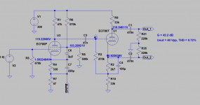
An example of ECF80 amplifier/cathodyne.
The only thing that the simulation shows a bit odd is that the screen voltage of the pentode section should be fine tuned to optimum THD (R6 or R8).
It is possible that in reality this is not needed.
The only thing that the simulation shows a bit odd is that the screen voltage of the pentode section should be fine tuned to optimum THD (R6 or R8).
It is possible that in reality this is not needed.
Attachments
Here are similar phase inverters.I started a new project to re-home a pair of OPTs from an old Scott 299 amplifier and am looking for PI circuit opinions/ideas. Ultralinear isn't an option with those transformers so I decided to experiment with a really stiff screen supply. It's an all-tube design except for the rectifiers but I'm really impressed with the performance of the regulator and anxious to hear it. I'm going to be using the 6P14P as the output tubes (the Scott 299 used 7189s originally) and it idles right at 500 volts on the anodes. There's lots of room for screen V adjustment within a range that still provides excellent regulation so I'll be doing lot of tinkering.
Anyway, the 299 used an ECF80 phase inverter and I've re-drawn the circuit (attached) but am wondering if anyone else has used this design and how it compares to some of the others. Chassis constraints limit me to a single 9 pin miniature tube so I guess I'm not "married" to the ECF80 if there's something that is a lot better, but I've read a lot of great stuff about the tube and I have a bunch so I planned to at least start out with it. What I don't know though is how the original Scott circuit design might compare sonically to some of the others. Yes, I know, opinions and tastes vary from person to person but having never heard a working Scott 299, I thought I'd ask the guys that play with this stuff more than I do. I've been into lots of guitar amp projects and amateur radio stuff but this is probably my first "hi fi" audio project so in that regard opinions are worthwhile to me.
Enough blabber. PI schematic attached. Many thanks in advance for your opinions, ideas, suggestions etc.
Attachments

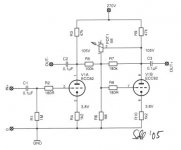
Are the schematics right? Isn't there a coupling capacitor missing somewhere? I would think that the grid of the right hand triode will sit at almost 100 V.
Addition: I think the schematics are wrong (see attachement).
Addition: I think the schematics are wrong (see attachement).
Attachments
You are absolutely correct. Whoever did those drawings forgot to include a cap to the 2nd grid. Also missed by the proof reader,Are the schematics right? Isn't there a coupling capacitor missing somewhere? I would think that the grid of the right hand triode will sit at almost 100 V.
Addition: I think the schematics are wrong (see attachement).
something I was exposed to while authoring articles for publication. I often got the sense the proof readers were college level English majors with no experience in electronics at all. In one case they had me inventing something at a time I would have been about five years old, Luckily I caught that one. In another case part of a line was left out by the printer, The meaning was entirely different, And on & on.
In spite of the greatest care there was still an error in the printed final paper product occasionally.
The configuration of those circuits is fairly common. Here it is with frequency selective components where it becomes a Baxandall
tone control.
Attachments

Aside from the tap on the grid side of the 220k grid resistor, which joins the other channel at the same point through a 1M pot (tapped at 500k with both the wiper and tap tied to ground - labeled "stereo balance") I've redrawn the circuit as is from a schematic I found online in a "service manual" for the 299. I'm curious to see the diagram you describe having 100k plate resistors.In the schematic in post #1 a grid return resistor of the pentode section is missing. Also the 220K resistor between the coupling capacitor and the control grid of the pentode section is too high in value for a grid stopper (in the Scott 299 the 220K resistor is paralleled by a 150 pF capacitor to boost the high frequencies a bit and is not functioning as a grid stopper).
Compared to the schematic of the Scott 299 your schematic uses 220K plate resistors against instead of 100K. What is the reason for that?
This looks worth experimenting with. Thank you!An example of ECF80 amplifier/cathodyne.
The only thing that the simulation shows a bit odd is that the screen voltage of the pentode section should be fine tuned to optimum THD (R6 or R8).
It is possible that in reality this is not needed.
- Home
- Amplifiers
- Tubes / Valves
- ECF80 phase inverter circuit