Hello,
I am building a Rod Elliott Phono stage for my setup. I am using the P05 power supply board and the P06 phono preamp board. Rod specifies that the P05 needs an AC supply from between 3 and 25V. I found a 16V 1000mA AC power pack from Jameco for this purpose. Here is the Link to the Jameco AC adapter. However I am having a hard time understanding the grounding as noted within Rod's schematic. On the P05 board there are three inputs, AC1, AC2 and ground. However any AC supply I have seen doesnt include a third ground wire, just hot and common. What am I supposed to connect to this grounding input?

I am building a Rod Elliott Phono stage for my setup. I am using the P05 power supply board and the P06 phono preamp board. Rod specifies that the P05 needs an AC supply from between 3 and 25V. I found a 16V 1000mA AC power pack from Jameco for this purpose. Here is the Link to the Jameco AC adapter. However I am having a hard time understanding the grounding as noted within Rod's schematic. On the P05 board there are three inputs, AC1, AC2 and ground. However any AC supply I have seen doesnt include a third ground wire, just hot and common. What am I supposed to connect to this grounding input?
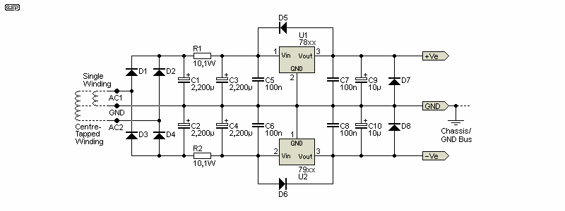
Did you miss Fig 1?What am I supposed to connect to this grounding input?
3-wire AC warts used to be common but all AC warts are going out of production. A 3-wire wart won't (can't!) use that type plug, and 3-wire plugs were never real standardized.
https://www.jameco.com/z/MGT-2450P-Jameco-Reliapro-50W-24V-2-1A-AC-to-AC-Screw-Terminal-Wall-Transformer_2229386.html
https://www.jameco.com/z/MGT-2440-Jameco-Reliapro-24-VAC-1600-mA-40-Watt-Wall-Adapter-Transformer_2230627.html
https://www.jameco.com/z/MGT-2440P-Jameco-Reliapro-24VAC-1-6A-40VA-Wall-Transformer-Screw-Terminal-3-Prong-White-PTC-Fuse_2318071.html
Thanks for the reply PRR. Im new to electronics and still learning. I really appreciate the feedback.
Im still confused about connecting a transformer to this power supply board. Does a single winding transformer connect between the GND and AC1? Or is using a two prong AC power brick simply not an option? The Jameco supplies you linked all seem to be grounded three prong products.
I am wondering if its worth getting a center tapped AC transformer and wiring it up myself instead of using a wall wart.
What do you recommend I do?
Thanks again I appreciate the help.
If you go with your originally suggested wall transformer connect its output to AC2 and GND , this will give you 1/2 wave rectified feeds to the 2 regulators which should be ok because you will only be lightly loading its output . Conversely a centre tapped transformer would connect to AC1 and AC2 with the centre tap going to the GND connection and would give full wave rectified feeds to the 2 regulators . If you used a centre tapped transformer and mounted it in a metal case then the case should be connected to safety ground via a 3 prong mains plug .
Is there any advantage of using a transformer instead of an external plug pack? In my (limited) thinking it would be advantageous to keep the transformer away from very small input signal of the preamp. Keeping that interference away from the signal path could be a good thing? However I am not sure if there are any real benefits to be had by using a center tapped transformer over the plug pack.If you go with your originally suggested wall transformer connect its output to AC2 and GND , this will give you 1/2 wave rectified feeds to the 2 regulators which should be ok because you will only be lightly loading its output . Conversely a centre tapped transformer would connect to AC1 and AC2 with the centre tap going to the GND connection and would give full wave rectified feeds to the 2 regulators . If you used a centre tapped transformer and mounted it in a metal case then the case should be connected to safety ground via a 3 prong mains plug .
I noticed in Rod's build photos he uses connections that are terminated with pins. They look similar to PC fan terminations. What are these pin/terminals called? it would be nice to build the preamp with connectors rather than point to point wiring incase I need to take it apart.
As I already stated using a centre tapped transformer will give full wave rectification ( more likely to give less rail ripple going into the regulators ) but as I also said the current load will be small so a wall transformer is likely to be adequate , I just cant say for sure that a single winding output wall transformer WILL be adequate . What I can say is Bob Cordell states in his book that he uses a wall transformer/ regulator configuration like you use are suggesting to drive various purpose built instruments . Yes the wall transformer by definition will keep induced hum away from the preamp circuitry but you could also mount a centre tapped transformer in its own steel case along with the regulator board and feed 15-0-15V DC via a wire umbilical cord to the preamp circuitry , also in its own steel case . The choice is yours .
I noticed in Rod's build photos he uses connections that are terminated with pins. They look similar to PC fan terminations. What are these pin/terminals called? it would be nice to build the preamp with connectors rather than point to point wiring incase I need to take it apart.
I know them as pluggable PCB headers and sockets , available with different numbers of pins and pin spacing.
Great, thanks for the info @epicyclic
I really appreciate you reiterating your point. I am still learning electronics and it takes me time to absorb that information.
Rod stated on his website that he used 2.54mm pitch connectors. I ordered some polarized male pin connectors that I can solder onto the board. I am not sure what kind of female cable attaches to this connection though, some searches didnt turn up much.
My current issues are the power jack and the power button. I am building a wooden enclosure out of 3/4" thick maple. Every 2.1mm barrel jack I have come across isnt nearly long enough to easily install it into the body of the enclosure. I thought about routing out the inside of the case to make more room for the connector but I am concerned that the wood remaining will be fragile because its so thin. I tossed around the idea of routing out a small area for an aluminum/stainless steel plate to mount the jack and inline fuse on but I would rather avoid that if possible.
Id like to use a "vandal" style button on the front of the case with an illuminated white ring. This has been surprisingly hard to find for a reasonable price. Mouser had some to the tune of $55 a pop, way more than I am willing to spend. If anyone has any suggestions let me know!
Thanks for the help everyone
For the power cable going from my custom +-15V DC power supply to my P06 phono preamp I used a "3-pin Mini DIN" panel mount connector (with a "3-pin Mini DIN" plug of course)
and as a power on/off switch I installed this DPST rocker switch: https://www.radioshack.com/products/dpst-125v-round-rocker-switch . The switch was installed on the P06 enclosure, not on the power supply enclosure, reason being that my power supply is at the back of my rack close to the wall outlet and not reachable (not easily at least).
So my power supply is always on, but my P06 on/off status is controlled by me via the DPST rocker switch I installed on its enclosure panel.
As per illumination, I use a nice (small and discrete) 2mm blue-ish LED on the front panel of the P06 enclosure which I drilled by myself.
You can use a "Rail Splitter" -- TLE2426 can provide 10mA which isn't quite sufficient (LM317/LM337 need at least 5mA to assure stability). See this nice write-up https://tangentsoft.net/elec/vgrounds.html
- Home
- Source & Line
- Analogue Source
- Help with ESP P05 Power Supply for ESP Phono Preamp P06