Power toroids are almost always wound with random wind equipment (and worst case, the two 115V primaries could be bifilar) so distributed capacitance is sky high. Going to a bigger toroid gets the turns reduced, but eventually lowers inductance faster than core area increase. (turns drop linearly with core area, So inductance = turns x turns /area goes down) So a bigger 115V primary toroid will at some point get worse for LF. The HF is already bad from distributed capacitance.
You likely get a center tap point from the two primaries, but no further taps for UL like taps, Lots of comments about power toroids working OK, until they actually measure the results or compare with a real OT. If Antek has trouble getting freq. response with a special winding approach, you can just imagine how an ordinary power toroid performs. (well, like the earlier Antek OTs that typically got returned )
If one is going to use power toroids, the approach to use is Circlotron, where only half as many turns are needed and no DC balance issues come up (well assuming the P-P tube biasing is right).
Please note that power transformers are designed for the mains voltage and mains frequency in your country. For example, here in Europe that's 230 V 50 Hz. Distortions are not taken into account at all. That means, with two transformers in series the biggest voltage is 460 V - at 50 Hz. For lower frequencies more turns are required. Otherwise either power capability sags ot the cores are driven into saturation.
Best regards!
Best regards!
I'm in the US, and the toroids I was looking at from antek are 115V in series or parallel for the primaries. so 230V center tapped. They're designed to be good for 50HZ and 60HZ mains, so slightly closer to the goal. I had read one opinion on why the (early?) Antek output toroids did so bad in the higher frequencies is that they designed for deepest low frequency response, and lost any good high frequency response as a result. My USB oscilloscope can do Bode plots, though not with any significant amount of power applied. I'm guessing this will give me a decent idea of high frequency response, but that bass will fall off more and more as power is increased in actual use. Planning to try to measure a few transformers with it tonight, and see what it does.
I wonder could one use half the primary of one transformer with half of the other in series and take advantage of this possible bifilar winding for better coupling? Tempting to buy one and unwind to see how they make them. The only problem with that is that I don't have an easy way to put lots of windings on a toroid to put it back together.Power toroids are almost always wound with random wind equipment (and worst case, the two 115V primaries could be bifilar) so distributed capacitance is sky high. Going to a bigger toroid gets the turns reduced, but eventually lowers inductance faster than core area increase.
So to get this straight regarding output impedances, The two transformers go with primaries essentially in series. Each one is 230V CT, so for calculating the secondaries, I will be looking at them as though the primary is 460V, so a 9V winding on one transformer would end up looking like a 4.5V winding? I'm thinking to design for 4ohms and add enough of a winding to make 8 ohms, or figure out where 4 ohms would be, and add a tap there. I just watched a guy wrap a new power toroid by hand, and it was less terrible than I would have imagined. Tedious, but doable.
If we look thru the activity on DIY to those people using toroids meant for 50/60 Hz they are mostly driving with triodes. The triode low rp easily drives most of the problems associated with these torrids. But they don’t solve for leakage reactance at all. It’s still in the audio path. So best avoid that solution entirely.Hi John,
If the OPT secondaries are put in series, will it cause performance to suffer? Or if I build with these power torroids with two windings, how about paralleling one from each transformer, with one or both from each transformer in series with the paralleled set?
easiest would be to design for only 4, or 8, or 16, but I'd like to be able to drive 8 ohm speakers, but retain the ability to use 4 ohm speakers too. I have ruled out for now using dissimilar transformers until I'm a little wiser and can better understand what the amp might do. I'm getting ready to finally purchase transformers for the 6080/6as7 amp you sent me the schematic for a few years back, and also want to build something with some 1625 tubes I've been carting around for years meaning to turn into an amp, and the crowhurst twin coupled seems a perfect match for them.
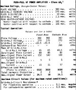
Next thing to decide is what tubes to use, the operating voltages & the plate to plate load impedance. For example if you were to use your 1625s for this project you could find recommended examples in the data for the 6L6 family of tubes. The 807 & 1625 are part of that family with the advantage of 30W dissipation. One of published settings in the RCA lists shews 360V plates, 270v screens in Class AB. ~26W before OPT losses. The recommended OPT primary is 6600 Ohms.
If your 1625s were used in the Crowhurst circuit each OPT would need a 3300 ct Ohm Primary & 16 &8 Ohm secondary. Paralleling the secondary’s gets 8 & 4 Ohms.
Using electrolytic caps to force tracking of the plate OPT to the cathode OPT allows the OPT secondaries to be connected in series. That is what I did to get the required load impedance. But that results in the impedance at the loudspeaker terminals to be 4X what they would be if parallel connected. I’ve made that point in the article I authored for AudioXpress. But my amp is strictly experimental; it spends most of its time on the shelf.
I’ve also built a Circlotron. But for that one Hammond built a special OPT for me. That article was also published in AudioXpress. It is nominally a 50W amp. All Hammond iron.
Pushed many tons of snow here today with the tractor. Might be more overnight. Not much time for toobz.
Attachments
It might be easiest to think in terms of winding ratios, or as suggested before, voltage ratios (same thing but measurable). Type 1625 is a classic sleeper, beautiful examples are still "a drug on the market", and it has a cathode, so you're backing a winner. 6L6 curves apply, so you don't have to re-invent the wheel.
The N. Crowhurst variation on Frank McIntosh's circuit has all the same strengths and weaknesses, and allows a single B+ supply, referenced to signal ground. The Circlotron, as recommended by smoking-amp, trades a great simplification in the signal path (both center-tapped primary windings are the same piece of wire!) for some complication in the B+ power supplies, and managable parasitic shunt capacitances (floating B+ supplies to signal ground and to AC input power). This seems to me like an excellent trade-off for your expressed openness to newer thoughts.
note: Bode plots are a theoretical construct, with imaginary asymptotic sharp corners, of magnitude and phase vs. frequency, plotted log-log. Oscilloscopes measure magnitude in real time. With frequency sweep they would measure signal magnitude vs. frequency. So, what they measure is not a Bode plot.
All good fortune,
Chris
Hi Chris, I won't profess to knowing the differences, but will read up on this. I'm just calling it what the people who sold the usb scope and the software were calling it. I originally got it to make impedance plots of speaker drivers. I read that it could be used similarly to measure flatness of output transformers curves. About to go hook it all up and find out!
Cool beans. So, the software will let you make sine waves of various frequencies using your computer's audio output? And also an automated sweep? That will be very handy indeed.
All good fortune,
Chris
All good fortune,
Chris
"If your 1625s were used in the Crowhurst circuit each OPT would need a 3300 ct Ohm Primary & 16 &8 Ohm secondary. Paralleling the secondary’s gets 8 & 4 Ohms."
I think I'm going to look at this as "doubling the primary impedance by putting the windings in series, cuts the secondary impedance in half". It will keep me from confusing that actually paralleling the secondaries doesn't change their impedance at all, just gives more copper in the output allowing more current to flow.
I'm looking to see how hard I can push a pair of these (within reason), while still getting decent sound out, so have been thinking about higher plate voltages, knowing all of that entails complications with filter capacitors needing to be put in series to not exceed their voltage ratings. Somehow getting up above 700 volts gets into scary territory for me, since true HV stuff starts to behave in unexpected ways for people not versed in the nuances. 700V ceiling also gives more than 20% margin on the maximum voltages for two 450V filter capacitors in series. I've poked around safely in a few power supplies and one amp now that push well past the normal 3-400V range, and feel confident (though more cautious than confident) that I will continue to use good judgement, such as hooking up test leads, and then turning on the power...
The biggest reason I can find why 807/1625 don't get used much is people like to leave their tubes exposed, and don't want that HV line to the plate cap out in the open. I would much prefer to put my amps in cases where the tubes are protected from pets, and visitors (and myself!). finding good sockets is also a PITA, but I've been collecting them up for some time now to have enough for a few projects.
Why have an 807 or 1625, and use it just like a 6L6, when you can take advantage of the extra oomph they have? There are specs in the tube manuals for AB2 at 80w output, and 120W if you're really into abusing the tubes. I think I will try for 50W from a pair with clean output in AB1, and see where things go from there. AB2, the drive wattage needed seems to be very minimal between .1 and .2 W, and ought to be easy to source. I've got two regulated healthkit supplies that will put out 800V when in series, which is yet another good reason to stop before crossing that line, but it will allow to push things a little farther when testing. I have an eico 1030 I have to rebuild still that can serve as screen supply, Bias supplies are available from all of these. It all boils down to the output iron in the end, but I think I will experiment first with cheap stuff, and if it all works, invest in something better if needed.
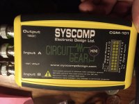
It's a 2mhz scope, with 11bit depth. It has it's own signal/function generator built in, and does all the maths to do FFT for spectrum analysis, and the frequency sweeps. It's the circuit gear mini from syscomp. sadly the gentleman who was the driving force behind this line of inexpensive but useful test gear passed away in 2018, and they don't seem to be producing new stuff anymore. I looked at picoscope stuff that John Stewart and some others use, but it was a little out of my budget at the moment. The picoscope has higher bit depth and better signal to noise ratio for FFT analysis, along with being just nicer stuff in general. I got the circuit gear mini dirt cheap off of eBay, still in the original package, but don't see them come up for sale often. I used last to monitor harmonic distortion out on an old HP200AB audio generator that I repaired, and amazingly it still is within spec, even after I repaired it 🙂Cool beans. So, the software will let you make sine waves of various frequencies using your computer's audio output? And also an automated sweep? That will be very handy indeed.
All good fortune,
Chris
For lower B+ (think safety) there are the TV Sweep tubes. They can do like 3x the current of most "audio" tubes. They use a lower primary Z OT typically. There are some cheap ones still, like 12/6GE5, 12/6JN6, 21HB5A, 17KV6A, (all cap-less), then bigger ones like 6HJ5 (cap-less but scarce now, Pete Millett's 50 W Amp ate them all up), 21LG6A, 6EX6, 6CB5A. The 12GE5 is $3 at Vacuumtubes.net and is nicely linear, 21LG6 is $4, 6EX6 and 6CB5 are $5, 21HB5 is $6, 17KV6 is $7, and 6HJ5 is $12. 6CB5 has been used in triode mode for SET Amps. The plate Watt ratings of the TV Sweeps can generally be multiplied by 1.33 for audio use. (for example, the 24 Watt 6HJ5 has as big a plate as the 35 Watt 6L6GC) You will want some N Fdbk, maybe just local, for these Beam Pentodes to get a good speaker damping factor. There is the Vertical Sweep 10/6JA5 (cap-less) which is quite linear, $3 for 10JA5. Curves like 7868, EL506 ...

Then there are big triodes like the V Regulator tubes. 6AS7, 6080, 5998, 6528, 6336... if you want low Ra without adding N Fdbk.

 I like the
I like the 17KV6 with its Edison style bulb, but it uses a hard to find Novar socket. (you typically have to take a Magnoval socket and tighten the socket pins)
Then there are big triodes like the V Regulator tubes. 6AS7, 6080, 5998, 6528, 6336... if you want low Ra without adding N Fdbk.
I like the 17KV6 with its Edison style bulb, but it uses a hard to find Novar socket. (you typically have to take a Magnoval socket and tighten the socket pins)
Last edited:
There is another version of the 6HJ5 with the same 12 pin socketing, slightly different pin-out, that looks interchangeable for new designs. Not in a Sylvania catalog, but is in the GE manual. Don't know if they're Raytheon or not - didn't need to buy any because a certain generous person, who cannot be named, but who's initials are S-A, gave us a heads up on the 6HJ5 curves a couple years back. That valve has only one letter difference from the 6HJ5, and is a 12ES pin-out.
All good fortune,
Chris
All good fortune,
Chris
I have a good pile of 6080 and 6as7. also some 6336 tubes, which are simply beautiful to look at. I’ve got a number of random sweep tubes. Wish I had thought to look for more of the sweep tubes when they were still dollar bin items!
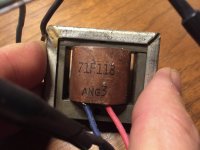
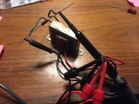
I’ve attached some pictures of the circuit gear mini, a baby SE transformer, the connections done crudly with a 15R resistor on my desk, and the frequency plot. The nasty stuff at the bottom is because I wanted to see what it looked like from DC on up, just for laughs. Not sure why it petered out at just 86.7khz, but it’s pretty flat all the way up according to this thing. The signal generator is built into the scope, and can only go up to 200khz, but that’s good enough. The scope is not 2mhz bandwidth, but rather up to 2M samples/s, at 11bits, which gives about 60db range for signal to noise measurements with the spectrum analyzer software, for noise and distortion measurements. It really is a shame that the designer is not with us anymore, but he left a pretty good trove of documents which explain how to use the equipment for useful purposes. He also made a curve tracer, which I’d like to find. this is not calibration lab grade stuff, but it’s very handy for experimenting. Gives nice plots of speakers, too, allowing to measure the resonant frequency and, also impedance response plotted against frequency.
Attachments
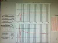
here’s a plot of a larger transformer, this one from an organ, I think. Bought a pair cheap from the auction site a while back, that will eventually get turned into something.
I think I’ll get a power toroid or two still just to measure the response. I am just toying around with this thing and the output transformers, so don’t know exactly how meaningful this data is, compared to the frequency response of the transformer in a real amp making power into a speaker. I imagine that the bass frequencies would drop off pretty heavy in the little single ended transformer with any real power through it. Do these nice flat curves indicate quality windings that will have flat response in the upper frequencies? The chart sadly doesn’t have very good markers showing the relative amplitude, but the cursor on the screen gives a readout when you put it on the chart. -1db at the upper end was about 40khz.
very neat with this, is you can sweep a preamp and see the response changes from the tone controls and filters in various settings. it can also show frequency response of a power amp into a load.
Attachments

Looks very cool indeed. So, it's a complete little interface between the cold cruel world and a USB connection to a computer? A sound card with a measurement mission. Seems like a great tool for an experimenter.
One note on measuring frequency response of transformers: because they have significant parasitic shunt reactances at the (interesting) frequency extremes, measurements need to be made with expected external impedances. For reasons of maintaining sanity, secondaries can be loaded by simple resistors, instead of actual loudspeakers (although that is also interesting for special needs speakers, electrostatics and such). The primary should be fed with an assumed realistic source resistance, usually much larger than your generator's 150R.
If you haven't decided on your output valves or their configuation (triode, partial triode, pentode, gain of two McCrowTron, "Schade" feedback, etc.) you could just take a middle value, maybe equal to the transformer's mid-band impedance with resistive rated load. 150R source will give unrealistically rosy results. And this is all still small signal - transformers are Tardis-dimentional beings.
All good fortune,
Chris
- Home
- Amplifiers
- Tubes / Valves
- crowhurst twin coupled amp with dissimilar output transformers