I've been wondering for a long time, if one had two sets of transformers that were not quite the same, say one set 4K to 8Ω, and one 2K to 8Ω, would the twin coupled output stage function with using the 4K in the plate side, and the 2K in the cathode side of the circuit, or vice versa? or do the transformers need to be identical type in order for the circuit to function properly?
I'm not sure why one might want to do this, other than not having a set of 4 output transformers, but perhaps there's benefit to it in some situations?
I'm not sure why one might want to do this, other than not having a set of 4 output transformers, but perhaps there's benefit to it in some situations?
It's possible, but there are a number of problems/complications that arise.
1st of all, it IS useful for changing the %CFB below 50%. However, combining the secondaries becomes a problem. Normally the Crowhurst Twin uses two identical xfmrs with the 16 Ohm secondaries combined to give an 8 Ohm output. With doubled power the output needs to put out 1.414 x the voltage, hence the need for the 16 Ohm secondaries.
With dissimilar xfmrs, you will have to compute the V and I at the secondaries for combining, and you may find that one xfmr has to change its primary Z in order for the output V's to match. Or you may need to change the secondary Z on one of them to something strange, say 12 Ohms, to get a match.
The two xfmrs will not be conveying half the power each either, if the primary Z's don't match, since they have to have equal tube currents. Then there are the cross coupling caps used in the Crowhurst Twin (from plate to opposite cathode), also used in many Mac designs as well (beside the bifilar stuff). These provide the cross coupling from Push to Pull sides. Won't work if the cathodes and plates are not swinging the same AC voltages.
One simplified scheme uses two identical xfmrs, with the tubes connected from plate ends of the top OT to crossed UL taps (for cathodes) on the lower OT. You can still use the cross coupling caps between the pimary ends or between the UL taps. The cathodes connected to 43% UL taps become 30% CFB (0.43 / 1.43 ). 16 Ohm secondaries get coupled for roughly 8 Ohm out (higher actually due to unequal power sharing), but the two xfmrs won't be carrying equal power. Not Optimal, but workable. Won't have the effective 2x the primary Z either. (actually more like 1X the primary Z, using the 16 Ohm secondaries in parallel for 8 Ohm output. You get 1.4x the primary turns for each tube, so 2X Zprimary, but the 16 Ohm secondaries paralleled give 1/2, so 1X result. This is useful though, since you end up with roughly the same primary Z, which probably was easier to find in the 1st place.)
Last edited:
Is there any advantage to be had from having the cathode transformer be the higher impedance of the two vs the lower impedance one? I really need to build one of these and poke around in it with meter and scope so I understand better what’s going on in them. Looking at getting some of the antek toroids to have a set of four the same, since there are a few possibly viable options there for $50/ channel, with the other option being to use one set of transformers I’ve got and just build a single Mono amp for now. Having two seta of transformers that I got relatively in expensively, got me wondering if anyone had ever built a crowhurst twin coupled amp like that With two different transformers per channel.
All of the commonly available OPTs have too high impedance to fill the requirements of Crowhursts Twin Coupled circuit.
Anything with a low enough impedance was designed for high power so is physically large & expensive.
I got part way around that problem by series connexion of the OPTs secondaries.
And the primaries are coupled using electrolytic capacitors, so that the cathodes & plates track each other.
That results in a damping factor a lot less than optimum. Purpose built OPTs would have fixed that.
But the first watt is less than 0.1% distortion & the amp clips at over 30 watts.
Not bad!! Think I posted some results recently, something we don't often see here.
Real test results using real test equipment seems to scare people away.
I was thinking 807/1625 tubes with relatively high voltage, total primary impedance between 4K and 6k. Pp Parallel transformers seem to be low enough impedance. I’ve got some random transformers out of an organ that are about 2k into 8R, and some others that are about 4k into 8R. Looking at the newer antek UL output transformers as an inexpensive way to properly build the John Stewart 6080 amp we discussed sometime back, I also got thinking about the crowhurst, but using 2 of the antek mains power transformer toroids per channel. The 20v mains toroids give about 2.1K into 16R, and using an online load line calculator, seemed to give pretty decent numbers for distortion at optimum plate voltage. Two of the 100va transformers ought to be able to handle 50W of audio comfortably. I need to look at the connections of the crowhurst output transformers to make sure I’m getting the right ones to be able to get both 4 and 8 ohm speaker connections. $24 ea for a mains transformer is affordable enough for experimenting, as is the $55 for the antek 15W rated output transformer. I’m not finding many actual reviews of these in use, so I may have to be the Guinea pig and try them out.
i recently rebuilt an old Scott 208, and feel a lot more confident in my understanding of the inner working of audio amplifiers (though I realize I’ve still got a lot to learn!), so I’m finally forging forward with some DIY amp building projects.
i recently rebuilt an old Scott 208, and feel a lot more confident in my understanding of the inner working of audio amplifiers (though I realize I’ve still got a lot to learn!), so I’m finally forging forward with some DIY amp building projects.
Of course you can. I'd insert the lower primary impedance transformer into the cathode leads and the higher ones into the plates', just to keep grid voltage swing low. In your case, if the primary impedance ratio is 1:2, the resulting output impedance will be the nominal values divided by sqrt 2.
Best regards!
Best regards!
Pardon my ignorance, but what would it have to do with grid voltage swing? I would prefer fixed bias over self bias for the twin coupled.
The grid, or drive voltage swing will be that of a usual design with grounded cathodes plus the cathode AC voltage.
Best regards!
Best regards!
Usually the desire is to use less than 50% CFB, since that is easier to drive. With 50% CFB you can easily end up with a 200V AC grid drive requirement (and linear). So a lower primary Z OT on the bottom is par for the course for lowering % CFB. I recommend NOT ordering any cheap OTs yet until the design is thoroughly checked over. Secondary voltages need to match up so they can be paralleled as a minimum. The Crowhurst Twin is one of the more complex designs, and going at it with different OT primary Z is really unexplored space. I recommend sticking with matched OTs with doubled secondary Z ( 16 Ohm for 8 Ohm out ) for a first try. Some UL taps on the OTs would allow trying unmatched primary Z later.
Also, check out Circlotron amplifier design too. For trying power xfmrs for OTs, Circlotron allows one to connect as many xfmrs in series to get the primary voltage requirement up to requirements. (it has no DC through the primary problem, and a -single- primary winding is all that is needed ie, 1/2 of a usual P-P OT primary ) The downside is the need for 2 floating B+ supplies and it is 50% CFB. At least those can be cheap xfmrs as well.
Also, check out Circlotron amplifier design too. For trying power xfmrs for OTs, Circlotron allows one to connect as many xfmrs in series to get the primary voltage requirement up to requirements. (it has no DC through the primary problem, and a -single- primary winding is all that is needed ie, 1/2 of a usual P-P OT primary ) The downside is the need for 2 floating B+ supplies and it is 50% CFB. At least those can be cheap xfmrs as well.
Last edited:
I used lundahl 1620s in a pair of twin coupled mono blocks. They use four separate coils to make up the primary, I used the two inner coils for the cathodes, and the two outs for the anodes, works well. 6K total impedance, so split up there is 3k cathode, and 3K anode.
I have been wondering whether the Twin Coupled has "effective" CFB at all;Usually the desire is to use less than 50% CFB ...
the emphasis is on "effective".
Doesn't the positive feedback from the opposite outputs plate back to the driver's load nullify the CFB ?
Positive FB inside a wider NFB loop does increase open loop gain, so NFB can be more effective;
but here both pos and neg FB work on the same stage ...
not shure how to prove or disprove this ...
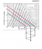
The proof becomes obvious when we measure an approximate drop of stage gain of about 14 db & the damping factor rises from obscurity to about 2. I've both measured & calculated the PFB to be ~2db. That is the same as Electrovoice claims in their similar PFB scheme. The driver stage gain increases since the bootstrapping creates a longer load line of higher impedance than is possible without the bootstrap. The blue trace is the extended loadline for the driver.I have been wondering whether the Twin Coupled has "effective" CFB at all;
the emphasis is on "effective".
Doesn't the positive feedback from the opposite outputs plate back to the driver's load nullify the CFB ?
Positive FB inside a wider NFB loop does increase open loop gain, so NFB can be more effective;
but here both pos and neg FB work on the same stage ...
not shure how to prove or disprove this ...
Attachments
I'm not convinced that you could use the crosscoupling with secondaries in parallel, because the different primary voltages would fight. With series secondaries, things would work themselves to a draw. Without crosscoupling, the whole thing falls apart.
If using beam tubes, an attractive option is to connect G2's directly to their own dedicated, considerably lower voltage, supply. Partial triode ("Ultra-Linear") operation is a good choice here for transmitting and sweep valves, which have less robust G2's than "audio" valves. Also works for McIntosh circuit.
All good fortune,
Chris
Almost sounds like you read the article I authored on Crowhurst’s amplifier. It was published in the Aug 2004 issue of AudioXpress magazine while it was still on paper. Not long after Ed Dell sold his publications they went on as webzines, no more paper. Surprising to me how few on DIY appear to have read AudioXpress & Glass Audio. Am I missing something?I'm not convinced that you could use the crosscoupling with secondaries in parallel, because the different primary voltages would fight. With series secondaries, things would work themselves to a draw. Without crosscoupling, the whole thing falls apart.
If using beam tubes, an attractive option is to connect G2's directly to their own dedicated, considerably lower voltage, supply. Partial triode ("Ultra-Linear") operation is a good choice here for transmitting and sweep valves, which have less robust G2's than "audio" valves. Also works for McIntosh circuit.
All good fortune,
Chris
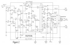
Throw enough money at a project & anything is possible. But this one is designed to use off the shelf parts in order to keep the cost down. Here are some of the main points on this version of Crowhurst’s Twin Coupled Amp.
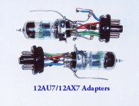
I tried both Crowhurst’s front end & a differential front end. Also tried are alternatives to the expensive 6SL7/6SN7s, the 6BQ7 family. The 6BQ7s performed well for a lot less $$$.
Attachments
-
 Twincoupled Amp D Nov6.jpg91 KB · Views: 134
 -
 Twin Coupled Amp Front for RHS Veiwing.jpg195.6 KB · Views: 129
 -
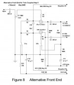 Figure 8 Alternative Front End.jpg64.5 KB · Views: 103
 -
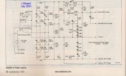 Figure 6 Power Supply Clone of Twin Coupled Amplifier w Caption.jpg213.4 KB · Views: 119
 -
 Crowhurst Twin Coupled Principle.jpg60.5 KB · Views: 113
 -
 6BQ7 Adapters E.jpg41.9 KB · Views: 101
 -
 Table A Twin Coupled Amp Performance Summary.jpg42.8 KB · Views: 99
 -
 Twin Coupled Amp Front for RHS Veiwing.jpg195.6 KB · Views: 128
I recommend NOT ordering any cheap OTs yet until the design is thoroughly checked over. Secondary voltages need to match up so they can be paralleled as a minimum. The Crowhurst Twin is one of the more complex designs, and going at it with different OT primary Z is really unexplored space. I recommend sticking with matched OTs with doubled secondary Z ( 16 Ohm for 8 Ohm out ) for a first try. Some UL taps on the OTs would allow trying unmatched primary Z later.
I already have these two sets of transformers, I wasn’t going to buy any more pairs that didn’t match. I am considering the inexpensive antek power toroids as outputs, for a twin coupled, however. Worst case, I have a few extra power transformers for other projects.
with regard to them, I was calculating possible impedances ratios earlier, and just realized I need to re-think some of that. Say it’s a 230v primary, pair of 10 volt secondaries. That makes a turns ratio of 23:1 from the primary windings to one of the secondaries. If those secondaries are in parallel, they simply can output more current, but it doesn’t change the turns ratio. Putting them in series cuts the turns ratio in half to 11.5:1, though. I’m needing to wrap my head around what happens when the primaries of the two transformers are essentiall in series, one in the cathode side of the circuit, one in the anode side. If I’ve calculated that the individual secondaries are 4 ohms, at 23:1 that would make the 230v primary of a single transformer equivalent to about 2125ohms. Then in series on a single transformer would make them 16 ohms, which is 11.5:1 correct?
Now if I have primaries of both transformers essentially in series in the circuit, that would make the primary seen by the tubes 4250ohms. with none of the secondaries connected to anything else yet, is this going to give me 4 secondary windings each at a turns ratio of 46:1 Primary to secondary? and putting those in series adds, but all in parallel they’re all just going to remain at 46:1 so they would be essentially 2ohm windings?
just want to confirm that I’m thinking about this clearly before I go thinking about this too much more!
In my unity-coupled amp, I made small boards for each output tube. On the board was a simple mosfet follower with gate fed from a voltage divider. Bottom of divider goes to the cathode, top of divider (and mosfet drain) go to opposite tube plate. Tubes with even the most fragile G2s can be used this way and it is much cheaper than doing something special with the iron like another winding.If using beam tubes, an attractive option is to connect G2's directly to their own dedicated, considerably lower voltage, supply. Partial triode ("Ultra-Linear") operation is a good choice here for transmitting and sweep valves, which have less robust G2's than "audio" valves. Also works for McIntosh circuit.
I vaguely remember seeing maybe one of the old unity-coupled schematics where there was something dropping voltage to the screen like a gas tube or something? I can't seem to find it now. I thought it was something big with lots of parallel tubes.
just want to confirm that I’m thinking about this clearly before I go thinking about this too much more!
If you figure the voltages at input and output sides, you just square that ratio to get the impedance ratio.
A good idea to check the current rating of the secondaries under normal use, then check under the new use (for full power). Getting that close will get the maximum performance from the OT's. And, of course, the original voltage ratings get reduced in the new scheme, depending on the lowest freq. versus the original 50 or 60 Hz rating. (core saturation effect)
Yes, for different Z xfmrs, you won't be able to use the cross coupling capacitors, like used in the Crowhurst Twin or Mac, unless one of the OTs has some taps that match the other OT. Using two matched OTs to begin with, with matching taps, can get you there for different primary Z, as long as the caps are between matching taps (and phased correcly).
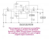
In Crowhurst’s first version the OPT secondaries are paralleled in order to force the plate OPT to track the cathode OPT. The HF coupling is accomplished by a pair of 0.5 microF caps (C6 & C7), thus a way around the total of leakage reactance between the two OPTs.If you figure the voltages at input and output sides, you just square that ratio to get the impedance ratio.
A good idea to check the current rating of the secondaries under normal use, then check under the new use (for full power). Getting that close will get the maximum performance from the OT's. And, of course, the original voltage ratings get reduced in the new scheme, depending on the lowest freq. versus the original 50 or 60 Hz rating. (core saturation effect)
Yes, for different Z xfmrs, you won't be able to use the cross coupling capacitors, like used in the Crowhurst Twin or Mac, unless one of the OTs has some taps that match the other OT. Using two matched OTs to begin with, with matching taps, can get you there for different primary Z, as long as the caps are between matching taps (and phased correcly).
If the OPTs are dissimilar the capacitor coupling can’t be used to defeat the leakage inductance, they are running at different audio levels on their primaries.
Could be a problem leading to HF instability.
Attachments
Thanks for this confirmation! I had originally started thinking about this in terms of resistance where in parallel two 4 ohm windings would give 2 ohms, but upon doing some calculations, that wasn't adding up somehow! 🙂If you figure the voltages at input and output sides, you just square that ratio to get the impedance ratio.
A good idea to check the current rating of the secondaries under normal use, then check under the new use (for full power). Getting that close will get the maximum performance from the OT's. And, of course, the original voltage ratings get reduced in the new scheme, depending on the lowest freq. versus the original 50 or 60 Hz rating. (core saturation effect)
Yes, for different Z xfmrs, you won't be able to use the cross coupling capacitors, like used in the Crowhurst Twin or Mac, unless one of the OTs has some taps that match the other OT. Using two matched OTs to begin with, with matching taps, can get you there for different primary Z, as long as the caps are between matching taps (and phased correcly).
I'm concluding from all of this that I need to get identical transformers for the twin coupled. I've sort of figured out what should be a good operating point for the tubes I want to use, and will pick some power toroids and see if they seem acceptable. Is there a rule of thumb for figuring how big a power toroid needs to be in order to get closer to 20-30hz? There seems to be a tradeoff, where the 100VA size is pretty good value for the money, and two of those for a twin coupled amp, would I be able to get 50W at 20-30 hz? If not, it's probably not that big a deal, since I'm leaning more and more towards 1 or more subwoofers handling the bottom two octaves or so in my system, and I don't have a room that really has enough space for truly deep bass without room effects setting in. Larger than the 100VA power toroids, and it seems like the windings won't be good enough to do upper frequencies well.
Hi John,In Crowhurst’s first version the OPT secondaries are paralleled in order to force the plate OPT to track the cathode OPT. The HF coupling is accomplished by a pair of 0.5 microF caps (C6 & C7), thus a way around the total of leakage reactance between the two OPTs.
If the OPTs are dissimilar the capacitor coupling can’t be used to defeat the leakage inductance, they are running at different audio levels on their primaries.
Could be a problem leading to HF instability.
If the OPT secondaries are put in series, will it cause performance to suffer? Or if I build with these power torroids with two windings, how about paralleling one from each transformer, with one or both from each transformer in series with the paralleled set?
easiest would be to design for only 4, or 8, or 16, but I'd like to be able to drive 8 ohm speakers, but retain the ability to use 4 ohm speakers too. I have ruled out for now using dissimilar transformers until I'm a little wiser and can better understand what the amp might do. I'm getting ready to finally purchase transformers for the 6080/6as7 amp you sent me the schematic for a few years back, and also want to build something with some 1625 tubes I've been carting around for years meaning to turn into an amp, and the crowhurst twin coupled seems a perfect match for them.
- Home
- Amplifiers
- Tubes / Valves
- crowhurst twin coupled amp with dissimilar output transformers