Hello,
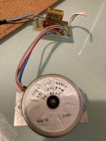
My old Rega turntable has a tired motor hence I got a new Premotec motor to replace it with. I am thinking to replace the old capacitor and resister too while I am replacing motor.
One thing that I am not sure about is if I can still use the same value capacitor and resistor for this Premotec motor. I am based in Australia and main voltage is 230v 50Hz.
Original Motor Serial Number : 9904 111 04802
Capacitor: Rifa 0.22uf 250v MKP cap
Resistor: Not sure what the original value was but when I measure it it shows 14.58K ohm
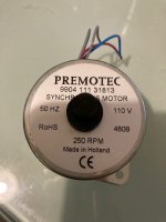
New Motor Serial Number: Premotec 9904 111 31813
Capacitor: I am thinking to use 2 paralleled 0.1uF, 300vac MKP caps = 0.2uF.
Resistor: 12K ohm resistor?
The reason I am thinking to reduce capacitor value is after reading this post. https://darklanternforowen.wordpress.com/2018/07/13/rega-planar-3-restoration/
According to the post, with slightly lower capacitance than stock, volts balance between windings is much improved and phase delay is not increased significantly.
Should I use 12K or 14K resistor for Premotec?
I have also attached original old motor with circuit board and new motor for reference.
Thank you very much for any guidance.
My old Rega turntable has a tired motor hence I got a new Premotec motor to replace it with. I am thinking to replace the old capacitor and resister too while I am replacing motor.
One thing that I am not sure about is if I can still use the same value capacitor and resistor for this Premotec motor. I am based in Australia and main voltage is 230v 50Hz.
Original Motor Serial Number : 9904 111 04802
Capacitor: Rifa 0.22uf 250v MKP cap
Resistor: Not sure what the original value was but when I measure it it shows 14.58K ohm
New Motor Serial Number: Premotec 9904 111 31813
Capacitor: I am thinking to use 2 paralleled 0.1uF, 300vac MKP caps = 0.2uF.
Resistor: 12K ohm resistor?
The reason I am thinking to reduce capacitor value is after reading this post. https://darklanternforowen.wordpress.com/2018/07/13/rega-planar-3-restoration/
According to the post, with slightly lower capacitance than stock, volts balance between windings is much improved and phase delay is not increased significantly.
Should I use 12K or 14K resistor for Premotec?
I have also attached original old motor with circuit board and new motor for reference.
Thank you very much for any guidance.
Attachments
According to the datasheet, you need 0.22uFd cap (2x 0.1uFd should be OK); the resistor should be 6K8.
It is rated at 18mA, so 6K8 would drop ~122.4V leaving 127.6 across the motor.
Thank you very much.
Super dumb question to ask... which connection diagram do i need to look at from attached connection diagram?
The motor is 110V and AC main is 230v (in AU). Do I refer right hand one (220 Vac 50 Hz: C= 0.22µF speed = 250 rpm)?
Attachments

I found that the latest iteration of 110v motor for Rega turntable was this one.
https://sparedparts.com/products/14915860
That one has 2 caps and 2 resistors. Not sure why they have two of each. Can anyone know why there are two of each and what their values might be?
Thank you.
https://sparedparts.com/products/14915860
That one has 2 caps and 2 resistors. Not sure why they have two of each. Can anyone know why there are two of each and what their values might be?
Thank you.
The right hand diagram is for 220VAC 50Hz operation.
The part you linked to with the PCB probably has different caps (and possibly resistors) for 33 and 45 RPM when using a synthesized power supply (50Hz/67.5Hz).
If you are using wall power, use the right hand diagram from the data sheet. If you want to run the motor at lower voltage than 127VAC, increase the resistor. The motor is rated for 18mA, so use Ohm's law (E=IR or R=E/I) to find the resistor value. If you need 110VAC at the motor and you start with 230VAC, then the resistor must drop 120V. 120/.018=6.666K, so 6.8K looks about right.
The right hand diagram is for 220VAC 50Hz operation.
The part you linked to with the PCB probably has different caps (and possibly resistors) for 33 and 45 RPM when using a synthesized power supply (50Hz/67.5Hz).
If you are using wall power, use the right hand diagram from the data sheet. If you want to run the motor at lower voltage than 127VAC, increase the resistor. The motor is rated for 18mA, so use Ohm's law (E=IR or R=E/I) to find the resistor value. If you need 110VAC at the motor and you start with 230VAC, then the resistor must drop 120V. 120/.018=6.666K, so 6.8K looks about right.
Thank you so much. That calculation really help me understand what value is required. Huge thanks.