I am currently breadboarding a tube regulated power supply based on Circuit 3 from Terry Bicknell's audioXpress article found here: https://audioxpress.com/assets/upload/files/bicknell2890.pdf It is intended for a 6N6P triode based line stage project I've been considering, and have calculated that the power supply needs to be capable of delivering 280V 65mA.
Here is the first version of the actual circuit as built. It uses an all Russian tube complement, a 5C4S rectifier (5Z4 equiv), a 6S19P regulator tube (replacing the EL84 in the Bicknell version), and a 6F1P (ECF80 equiv). A couple of resistor values are slightly different than the original schematic as I was just using what I had on hand.

Included are the voltage readings I took while it was operating. I connected the power supply to a 3300 ohm resistive load and was able to max out the B+ at 275V with it delivering 83mA.
Not knowing what to expect I was surprised how much current the regulation circuit itself consumed in operation. About 22mA if my interpretation is correct. So, I went about attempting to alter the circuit looking to preserve (as much as possible) some of those precious milliamps. Below is the new schematic.

The changes made are as follows:
1. Added another resistor to the voltage divider R10/R11 and brought the heater elevation connection for the 6F1P to this point, eliminating the separate divider originally used for that purpose. The increased resistance halved the current draw.
2. Increased the value of R14, while hopefully still supplying the zener diode with enough current to operate. That is the purpose of this current, is it not?
3. Removed the zener diodes from the adjustment circuit and implemented a more traditional(?) high resistance voltage divider, claiming back over 3mA.
The above changes reduced the overall current usage to about 16mA and I was then able to push the regulator slightly higher to 283V & 85mA into the same 3.3K load. Unfortunately that's the only power resistor I have to test with at the moment.
Anyway, I was wondering if anyone had any critiques/insights regarding my tube choice, or the original/modified versions of the circuit. I myself have just enough knowledge to be dangerous, but not much more.
I would be particularly interested in comments about the running of the 6S19P and 6F1P heaters from the same 6.3V winding and the elevation voltage chosen. The 6S19P has a Vhk of 250V and the 6F1P 100V (provided it's the same as the ECF80). With the cathode of the 6S19P at 280V and the 6F1P at 100V I decided 160V would be appropriate, but I'm keen to hear other opinions.

Here is the first version of the actual circuit as built. It uses an all Russian tube complement, a 5C4S rectifier (5Z4 equiv), a 6S19P regulator tube (replacing the EL84 in the Bicknell version), and a 6F1P (ECF80 equiv). A couple of resistor values are slightly different than the original schematic as I was just using what I had on hand.
Included are the voltage readings I took while it was operating. I connected the power supply to a 3300 ohm resistive load and was able to max out the B+ at 275V with it delivering 83mA.
Not knowing what to expect I was surprised how much current the regulation circuit itself consumed in operation. About 22mA if my interpretation is correct. So, I went about attempting to alter the circuit looking to preserve (as much as possible) some of those precious milliamps. Below is the new schematic.
The changes made are as follows:
1. Added another resistor to the voltage divider R10/R11 and brought the heater elevation connection for the 6F1P to this point, eliminating the separate divider originally used for that purpose. The increased resistance halved the current draw.
2. Increased the value of R14, while hopefully still supplying the zener diode with enough current to operate. That is the purpose of this current, is it not?
3. Removed the zener diodes from the adjustment circuit and implemented a more traditional(?) high resistance voltage divider, claiming back over 3mA.
The above changes reduced the overall current usage to about 16mA and I was then able to push the regulator slightly higher to 283V & 85mA into the same 3.3K load. Unfortunately that's the only power resistor I have to test with at the moment.
Anyway, I was wondering if anyone had any critiques/insights regarding my tube choice, or the original/modified versions of the circuit. I myself have just enough knowledge to be dangerous, but not much more.
I would be particularly interested in comments about the running of the 6S19P and 6F1P heaters from the same 6.3V winding and the elevation voltage chosen. The 6S19P has a Vhk of 250V and the 6F1P 100V (provided it's the same as the ECF80). With the cathode of the 6S19P at 280V and the 6F1P at 100V I decided 160V would be appropriate, but I'm keen to hear other opinions.
So 22-16 is 6mA saved. At nominal 325V feed you have saved nearly 2 Watts. At my electric rate you save $0.000,4 per hour, or 2 dollars over the notional 5,000 hours between tube replacement (@>$20?), or 3 years at 5 hours/night.reduced the overall current usage to about 16mA
I admire the goal, and think you have done well to save the planet, but this is hard-won savings just in think-time and re-wiring time. OTOH a couple MOSFETs would lose many Watts of heater power.... just saying.
What strikes me odd is pre-regulator voltage 505V no-load, 460V reg-only, 328V full load. 177V or 35% drop is a lot. Seems to be 1.7K of dead resistance in there. The 220r and 100r (why both?) resistors count about 6X because pulsating waveshape. Rectifier is hundreds-Ohm again at a bad point. OK, even without choke we may have 1k-2k series. And there is near 18 Watts of lost power (heat) in these losses, dwarfing what you managed to save in trimmed circuitry. Yes to arrive at 275V with this transformer you have to lose about that much; but has every Watt contributed to filtering? Is it really cleaner than a C-R-C-R-C-R-C filter made of $1 caps? (Yes, caps don't glow.) (And yes, you already built this, and it is beautiful.)
Yes, you make excellent points of course. And I suppose 6mA is a tiny fraction to be nitpicking over, but it did give a slight bump to the output power which is what the point of the experiment was. I enjoyed the tinkering at least.
I'll have to look again at what may be contributing to the large voltage drop at full load. It did seem like a lot, but I haven't had that much experience with tube rectifiers to know if it's abnormal (for the 5C4S or in general). The 220R resistors were mainly to give me something to measure across, so I might whip them out first.
During the time spent probing this circuit I was quite pleased with how stable the output from the rectifier+filter was by itself - sans regulator - so I may ditch the later all together. But then, what would all those hours of reading about tube regulators be for?!
Just a thought, could the choke core saturating be responsible for the voltage drop? It's rated 80mA but I've been chucking 100mA through it.
It wasn't. 😉
I've taken a few more readings of the rectifier voltage drops and here are the results.
Unloaded, regulator disconnected: current=10mA
520VAC peak (368VAC rms) into the 5C4S, 510VDC out =10V drop
3.3K ohm load, regulator disconnected: current=100mA
492VAC peak (348VAC rms) into the 5C4S, 373VDC out =119V drop
Unloaded, regulator connected: current=20mA
516VAC peak (365VAC rms) into the 5C4S, 472VDC out =44V drop
3.3K ohm load, regulator connected: current=100mA
492VAC peak (348VAC rms) into the 5C4S, 375VDC out =117V drop
Assuming I'm calculating the voltage drop correctly, is this relatively expected behavior?
The 5Z4 datasheet would suggest at 100mA load and 350VAC rms on each plate the result should be around 420VDC output (if I'm reading it correctly), so a 70Vish drop rather than 120. The 5C4S datasheet reads similarly.
I may convert to choke input and see what happens.
You could load the pentode section with a 10M45S/DN2540 to increase loop gain.
If you use a single EF184 you CAN run the heaters from the same supply given that the voltage between output and cathode of the single error amplifier is not more than 250V
Also remove R3 and make the plate resistors of the 5Z4 120 Ohm or so, no need for such a saggy supply with a tube regulator.
Also see https://www.diyaudio.com/community/threads/tube-power-regulator.381945/ on the same topic
Thanks v4lve lover. I came across your 6S19P design & PCB while researching this topic.
How would a EF80 compare with the EF184? I already have some of the former. Just to be clear, are you also saying the 6S19P & ECF80 heaters in my current circuit shouldn't be run off the same winding?
To be honest, the power supply was designed to be saggy, as I wanted 380V into the regulator for 280V out - a 100V differential. I remember now that I put in the plate resistors to bring the input AC voltage down below the 5Z4 rating of 350V for cap input due to my transformer being slightly overpowered. That's the other reason the power supply was made to drop so much voltage.
The 120V voltage drop across the rectifier tube is unanticipated though. Maybe it's just a bad tube? A PSUD sim of the circuit suggests I should be getting 50V more than I am out of the 5C4S.
Thanks for your time!
Last edited:
Well if the soviet equivalent of the ECF80 follows the western datasheet, your circuit puts the cathodes of the triode and pentode half at 180V or so with regards to the output. Wheras the maximum of both the ECF80 and 6S19P is 100V heater to cathode, even if you divided up the difference, which you did by placing the divider at 150V your still putting the 6S19P heaters at negative 125V to cathode, over its maximum spec of 100V if memory serves me right*.
If you up the divider to 200V its within spec, but i trust a EF184 or EF80 more with its 250V rating heater to cathode.
*Every factory had its own datasheet i beleive and they are all slightly different, but 100V stuck in my head,
In any case, if you use a 150V reference tube, and a EF184/80 you can just tie the heater to the cathode of the 6S19P and be done with it, because those western tv tubes where made for 250V continuous.
However, i think a single EF184 CCS loaded may have superior AC performance over a pentode half of ECF80. Just considering EF184 is a frame grid tube, and hence very high gain once you CCS load it with something with very high internal resistance *DN2540 cascode or a BJT cascode.
Fun fact, did you know that a triode connected EL36 has a RI of 340 ohms or so, which is nearly identical to 6S19P but a higher transconductance, giving superior step-load performance. and nearly twice the anode dissipation at only 1.5X heater power. /OT mode off.
6P41S somehow strikes me as a great regulator tube too.
I do have some 6P14P (EL84 equiv) that I bought for this circuit as an alternative to the 6S19P. I'll look and see if it might have similar benefits to the EL36.
I could replace the pentode part of the 6F1P with an EF184, and then maybe find a separate triode replacement (maybe the EC86?, which I have the Russian equiv 6S3P) couldn't I? I also have some 6F3P (6BM8 equiv) so can investigate them compared to the 6F1P.
I could replace the pentode part of the 6F1P with an EF184, and then maybe find a separate triode replacement (maybe the EC86?, which I have the Russian equiv 6S3P) couldn't I? I also have some 6F3P (6BM8 equiv) so can investigate them compared to the 6F1P.
This circuit is good, but does have its limitations, essentially what you are doing is creating a reference voltage with the triode half whose output impedance is 1/transconductance in parallel with the tail resistor. The pentode half will have a unbiased virtual cathode resistor of 1/transconductance again, Looking at it from an AC point of view. So for maximum error amplifier gain, you want some reference voltage that is very low impedance at the cathode. And very low noise.
Now i know a 85A2 is VERY VERY Low noise, has a Z of about 300 ohms, is this better as a triode half of a ECF80? that depends on the current and frequency, as you can bypass the 85A2 with approx 47nF so at higher frequencies the impedance decreases.
A zener diode at the cathode allows for very large capacitance values that increases gain somewhat, without forming a relaxation oscillator as would be the case with a 85A2 or 0A2.
You can cascode two 12AX7 total gain will be approx 3000. with better DC stability as a single cascode loaded EF184. But adding stages slows down the regulator in its ability to respond quickly to load shifts.
Best i could come up with at the time was EL34 in triode for decent gain ,efficiency and availability. controlled by a BJT cascode that was fed from the rectified EL34 heaters, giving maximum efficiency and very high loop gain in the system. The EL34 also has good transconductance, so its ability to function as a glorified cathode follower is quite good.
EL84 is certainly going to be higher mu in triode than a 6S19P and give lower output noise, but at the cost of 50-60V extra drop over the regulator to account for low line conditions. This could work if you design around 150V nominal Anode-cathode, and provide perhaps 10K of bypass resistance from anode to cathode, as not to stress the cathode too much by high continuous DC current.
That is another thing that is seldom talked about, you can bypass most regulators with a resistor if you have a known minimum current requirement.
But then, what would all those hours of reading about tube regulators be for?!
I enjoyed the tinkering at least......
Steady loads like preamps, and "steady" wall power suitable for incandescent lamps, I've never seen much need for regulation. With modern cap prices a 4RC filter gets ripple down in thermal hiss.
@v4lve lover, you've given me much to consider and I appreciate the time that you've taken to write. The main reason I chose that particular circuit from the Bicknell article was that it performed slightly better than the 'traditional' regulator circuit (Circuit 1) without being too far away from it conceptually. I'm a bit of a dunce and it took me quite a while to get a handle on the workings of tube regulators to begin with. (Thank you John Atwood!)
The preamp I'm considering is the CCDA, so a steady load indeed. I very much like the idea of B+ being unaffected by line voltage variation, but simplifying down to a rectifier/filter circuit and the associated efficiency gain is appealing also.Steady loads like preamps, and "steady" wall power suitable for incandescent lamps, I've never seen much need for regulation. With modern cap prices a 4RC filter gets ripple down in thermal hiss.
Someone mentioned the cascoded diff. Pair, this one is also in Bricknell’s article. Works extremely well! It has tight regulation, low output impedance, and very low noise. A couple of 6N2P’s would be good subs also. I’ve used this one several times.
Attachments

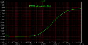
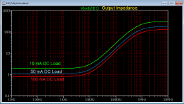
Just simulating this. (6267 is the equivalent of EF86). Output impedance is stable through a range of loads, PSRR -60dB. Note PSRR is measured without the input filter.
Attachments
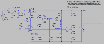
Is there a specific reason for leaving out C4 and reducing C47 from 470n to 47n? I thought that C4 and C47 contribute to noise reduction.
- Home
- Amplifiers
- Power Supplies
- Looking for opinions on this 6S19P tube based regulator