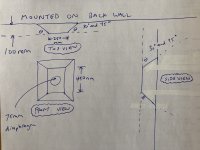
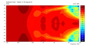
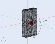
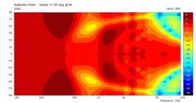
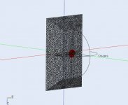
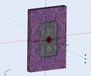
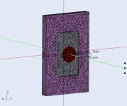
Right now, I'm having a pretty frustrating issue with gmsh -> Akabak where the meshed model doesn't show up properly in Akabak; I think it's on the gmsh end but while I try to sort that out, I'm wondering if anyone can help me run some sims from 100 Hz to 10 kHz for the on-axis response of an ideal driver, including the effect of baffle step from the geometries in the images below? Assume the back wall is infinitely large.
Two sims please, if possible - one with baffle edge chamfers at 30 degrees all around, and one with chamfers at 45 degrees all around. For reference, 0 degrees would be no chamfers, i.e. infinite baffle, and 90 degrees would be like a regular rectangular box.
EDIT: Sorry for the white-out tape, I made some dumb mistakes while sketching in a rush. Never sketch in a rush if you can help it!
Attachments
Last edited:

Make sure you are using the right formatRight now, I'm having a pretty frustrating issue with gmsh -> Akabak where the meshed model doesn't show up properly in Akabak; I think it's on the gmsh end
"Mesh-Files
Note, only text-mesh-files of version 2.2 are supported. Saving the 2D-mesh-file:
In GMSH 4 go to menu File/Export..., select File-Type = GMSH, eventually select Version 2 ASCII.
In GMSH 3 simply issue menu File/Save mesh-file.
(GMSH3 is still available from GMSH web-site, use version 3.0.6 from http://gmsh.info//bin/Windows/)"
No problem.Yes, sticking out of the wall, haha. Thanks so much for deciding to help out!
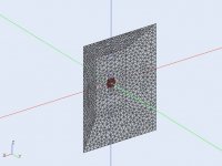
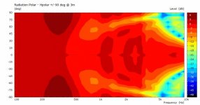
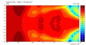
This is the 30deg.
Attachments
Thanks fluid, will try to get a look at this tonight. It might be this, since my model (visualization/preview) just doesn't appear at all when loading up the mesh file.Make sure you are using the right format
"Mesh-Files
Note, only text-mesh-files of version 2.2 are supported. Saving the 2D-mesh-file:
In GMSH 4 go to menu File/Export..., select File-Type = GMSH, eventually select Version 2 ASCII.
In GMSH 3 simply issue menu File/Save mesh-file.
(GMSH3 is still available from GMSH web-site, use version 3.0.6 from http://gmsh.info//bin/Windows/)"
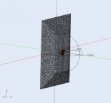
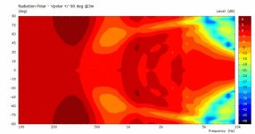
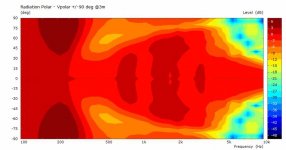
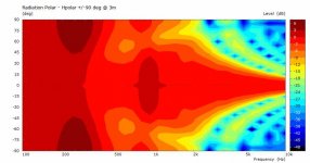
Awesome, thanks a lot DonVK.... and the 45deg
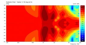
Trying to figure this out... the response has a bit more output on-axis below 400-450 Hz? Or, another way to put it, there's a shelf on-axis between ~400 Hz and ~800 Hz... in general it seems like there's no baffle step per se and that the response is +/- 1.5 dB on-axis up until the driver(s) start to beam, but that verticals are worse than horizontals. Very interesting result, will play around with it more myself once I get this sorted out.
I am going to guess that having 20 (or 22.5) degree chamfers will lead to an even smoother result.
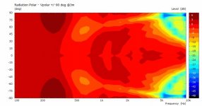
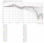
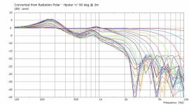
There are a few things going on. Sometimes easier to see in the curves. These curves (45deg baffle) are normalized to 0 deg like the polar contours. So the flat line is always at 0 deg, and everything else is relative to it.
At some low freq the reflection from the IB is "in phase" with the radiator, so no off axis difference. The diffraction at higher freq shows up off axis, sometimes in phase (additive) and others not (subtractive) depending on the geometries. The slope of change (4pi to 2pi) and the over/undershoot amplitudes are a function of the ratio of driver diameter to baffle [width, height, depth) and frequency (wavelength). Once the driver starts to radiate in 2pi space the baffle is ignored and the beamwidth narrows and off axis deteriorates.
[edit] Are you trying to get a smooth response from a wall mount driver? or interested in the effect of the chamfer angle?
Attachments
Last edited:
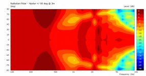
Yes to both. I want to see what could be done (within reason) to get smooth response, on- and off-axis, from nearfield monitors mounted on wall. Tons of absorption could do it, but I want to see how, or if, it could be done with a no-damping approach.[edit] Are you trying to get a smooth response from a wall mount driver? or interested in the effect of the chamfer angle?
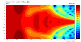
Here's a few examples with damping material (~8cm FG) around the baffle (with R25mm roundover).
The sloped sides (30deg) actually do a reasonable job as well. I wanted to see what the rectangular box with external damping looked like.
The sloped sides (30deg) actually do a reasonable job as well. I wanted to see what the rectangular box with external damping looked like.
Attachments

Thanks DonVK
With version 2 ASCII I got the pre-vis to show up but that's about it. Man, this is not a user-friendly piece of software, even if it is much easier than what it used to be.
With version 2 ASCII I got the pre-vis to show up but that's about it. Man, this is not a user-friendly piece of software, even if it is much easier than what it used to be.
No problem to lend a hand. Usually I try to keep the speakers away from the wall 🙂
In some ways I prefer the text files of ABEC because I could cut&paste for variants. The AKABAK GUI is more mouse clicks but it helps guide you. It's especially nice in the way it packages all the files in one project (portability). It is worth the learning curve.
PM sent.
In some ways I prefer the text files of ABEC because I could cut&paste for variants. The AKABAK GUI is more mouse clicks but it helps guide you. It's especially nice in the way it packages all the files in one project (portability). It is worth the learning curve.
PM sent.
You do have to get your head around it but once you are there it does make sense.Man, this is not a user-friendly piece of software, even if it is much easier than what it used to be.
Have you seen this video? A good walkthrough of getting AKABAK going.
Yes, multiple times actually but I think it's not really geared toward a first-time user unfortunately. Seems like a number of steps are glossed over, and it's not completely comprehensive as far as what can go wrong.You do have to get your head around it but once you are there it does make sense.
Have you seen this video? A good walkthrough of getting AKABAK going.
The damping around the box, in theory, would attentuate the back-wall reflection for off-axis listening that comes from the offset between the baffle and the backwall. But 8 cm wouldn't be enough for that. https://www.jochenschulz.me/en/blog/rockwool-glasswool-hemp-best-absorber-material seems like you'd want at least 6" or 8" to make a real dent in it (low-density FG as opposed to high-density).Here's a few examples with damping material (~8cm FG) around the baffle (with R25mm roundover).
The sloped sides (30deg) actually do a reasonable job as well. I wanted to see what the rectangular box with external damping looked like.
Above baffle step, though, you'd really need damping on the baffle itself in order to mitigate diffraction effects from the baffle edges.
- Home
- Loudspeakers
- Multi-Way
- Trying to simulate baffle step in Akabak