I'm hoping someone can help me with two questions on this simple circuit...
1) To parallel these grids I have two choices, 1. a simple series string like what is shown with one stopper or 2. each tube with its own grid stopper all terminating at a common star at the input. I'm assuming this wired series string is ok with just a single grid stopper at the beginning. (series stringing grid stopers isn't an option because the stoppers would sum across the five tubes progressively different per tube). Which would you do, like its written or star-join dedicated stoppers?
2) Do I really need 1000 uF bypass capacitors? What is the smallest Ck value do you think I can use here where the difference is inaudible from using 1000 uF? Is there a simple computation for Ck without simply always just "making them big"?
Best to use one grid resistor per grid. I think that's more of a conceptual diagram than a schematic.
The 400R // 1000uF cathode circuit gives 0.4Hz, so you could bump that up to 2Hz using a 220uF instead.
Use a Nichicon UES series 220uF at 25V.
f = 1 / ( 2Pi x R x C ) approximately, neglecting the tube cathode impedance which will raise the f up some.
The 400R // 1000uF cathode circuit gives 0.4Hz, so you could bump that up to 2Hz using a 220uF instead.
Use a Nichicon UES series 220uF at 25V.
f = 1 / ( 2Pi x R x C ) approximately, neglecting the tube cathode impedance which will raise the f up some.
Last edited:
Best to use one grid resistor per grid. I think that's more of a conceptual diagram than a schematic.
The 400R // 1000uF cathode circuit gives 0.4Hz, so you could bump that up to 2Hz using a 220uF instead.
Use a Nichicon UES series 220uF at 25V.
f = 1 / ( 2Pi x R x C ) approximately, neglecting the tube cathode impedance which will raise the f up some.
Thanks! Star parallel with stoppers it is then. The 220uF reduction really helps, I wanted to parallel each Ck with a 22uF or so Solen film cap (depending on PCB room), but figured the 1000uF shown would "swamp" it too much, but 220 uF is closer to the film cap value of 22 uF.
All this recent talk of using DC Links for Ck is nice, but that's expensive when you need 220uF x 10 DC links! So I was going to bypass each electro with something in the under 22 uF range film cap. Kind of a "poor mans" DC Link Ck approach I guess.
Just keep each grid resistor right at the grid it connects to, then daisy chain.
I don't think you'll need bypassing if you use the Nichicon UES capacitors.
I don't think you'll need bypassing if you use the Nichicon UES capacitors.
Thanks Rayma,
Here is what I'm thinking so far, just did this today, while the wife is babysitting...
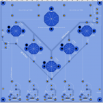
The stoppers will be soldered directly to the socket pins with no more than an .125 inch of wire, then jumpered into the PCB "grid bus". I can do it this way because I decided to use panel mount sockets but on a PCB, by routing 20mm holes for each socket. Here is the start of what I'm thinking for the five tubes in a "V" shape just the way Broskie "imagined" in the old article. This is nowhere near complete, just where I'm at as of starting this PCB a few hours ago and getting your advice. The entire topside is unbroken copper, all traces are on the bottom, sockets screw onto bottom on nylon standoffs with their pointing pins up through the 20mm routed holes to the top side for wiring. The cathodes I'm setting up for either Rk's or LM317's (builder choice), each Rk has a rectangular hole routed under it, this hole also provides airflow if using CCS's. All the CCS's (if one goes that way) are on the board edge so one angle extrusion of aluminum can heatsink them all. The screen strapping resistors will be soldered direct to the socket pins too just like the stoppers, then each plate pin jumpers into the "plate bus". The filaments all arrive via the back side and jump into the holes near pins 4/5, those basically "fly in" carefully above the board backside. I want to see a big ST rectifier behind the "V", this will be to make the B+ slow start. But the toroid, diodes and first reservoir will NOT be on the board, those will be elsewhere in the chassis. So basically I might be bringing pulsating DC to the board and doing the last two RC filters there with the damper (or rect) tube starting that chain. Undecided, but I do have room for two 57.5 x 35 DC links as the two RC filters that are on the board. I specifically dont want the diodes, toroid or reservoir C1 on the board.
This is kind of a hybrid of point to point and PCB first time I tried this, I'm liking it. grid and screen resistors are on the sockets, filaments fly in from back, cathodes jumper to each Ck circuit at the edge. I still have room to do film bypasses on the Ck electros, those are set up for 18mm / 7.5 pitch high quality electros like Elna SILMIC or the Nichicons you suggested.
NOT COMPLETED, in progress view:

Here is what I'm thinking so far, just did this today, while the wife is babysitting...
The stoppers will be soldered directly to the socket pins with no more than an .125 inch of wire, then jumpered into the PCB "grid bus". I can do it this way because I decided to use panel mount sockets but on a PCB, by routing 20mm holes for each socket. Here is the start of what I'm thinking for the five tubes in a "V" shape just the way Broskie "imagined" in the old article. This is nowhere near complete, just where I'm at as of starting this PCB a few hours ago and getting your advice. The entire topside is unbroken copper, all traces are on the bottom, sockets screw onto bottom on nylon standoffs with their pointing pins up through the 20mm routed holes to the top side for wiring. The cathodes I'm setting up for either Rk's or LM317's (builder choice), each Rk has a rectangular hole routed under it, this hole also provides airflow if using CCS's. All the CCS's (if one goes that way) are on the board edge so one angle extrusion of aluminum can heatsink them all. The screen strapping resistors will be soldered direct to the socket pins too just like the stoppers, then each plate pin jumpers into the "plate bus". The filaments all arrive via the back side and jump into the holes near pins 4/5, those basically "fly in" carefully above the board backside. I want to see a big ST rectifier behind the "V", this will be to make the B+ slow start. But the toroid, diodes and first reservoir will NOT be on the board, those will be elsewhere in the chassis. So basically I might be bringing pulsating DC to the board and doing the last two RC filters there with the damper (or rect) tube starting that chain. Undecided, but I do have room for two 57.5 x 35 DC links as the two RC filters that are on the board. I specifically dont want the diodes, toroid or reservoir C1 on the board.
This is kind of a hybrid of point to point and PCB first time I tried this, I'm liking it. grid and screen resistors are on the sockets, filaments fly in from back, cathodes jumper to each Ck circuit at the edge. I still have room to do film bypasses on the Ck electros, those are set up for 18mm / 7.5 pitch high quality electros like Elna SILMIC or the Nichicons you suggested.
NOT COMPLETED, in progress view:
Attachments
If turning the pentodes into triodes you may want to consider the Bill Perkins (Pearl-Hifi) attached article. O H Schade mentioned in his article "beam power tubes" that for optimum performance the screen should be 15-20V below the plate. Spannenberg mentioned the same. I'm using it in UL and it makes a marked difference in distortion numbers. As usual YMMV.
In private correspondence Bill mentioned a single 1/2 watt zener will do, I am using a 22V zener with an EL506 (7868 / 7591) which is basically a beefed up EL84 but as a beam power tube rather than pentode.
In private correspondence Bill mentioned a single 1/2 watt zener will do, I am using a 22V zener with an EL506 (7868 / 7591) which is basically a beefed up EL84 but as a beam power tube rather than pentode.
Attachments
If turning the pentodes into triodes you may want to consider the Bill Perkins (Pearl-Hifi) attached article. O H Schade mentioned in his article "beam power tubes" that for optimum performance the screen should be 15-20V below the plate. Spannenberg mentioned the same. I'm using it in UL and it makes a marked difference in distortion numbers. As usual YMMV.
In private correspondence Bill mentioned a single 1/2 watt zener will do, I am using a 22V zener with an EL506 (7868 / 7591) which is basically a beefed up EL84 but as a beam power tube rather than pentode.
Thanks! I saved that to the folder I have going for this project. I'll have to study it. As you can see I have plenty of room on the board to at least footprint this way of strapping the tube, then a person can build it with a simple resistor between pins 7 and 9, or they can jumper into this little circuit footprinted next to each tube. Once the board is made its just a matter of experimenting / deciding which way to go, with no need for a different board. This is how I did the Kathode circuits here, you can build it with LM317's or you can build it with Rk's.
Also worth mentioning, for this project I'm planning on using a 16V switching PS for the filaments with a 13 ohm resistor to each individual tube (aluminum resistors heat sinked elsewhere in the chassis). This way a person can plug in any voltage tube they want, 6BQ5, 8BQ5 or 10BQ5. (I own a lot of 10 and 8 volt xBQ5 tubes). This suggestion came courtesy of Tom Bavis in another thread when I was just thinking about how to heat all these tubes and be able to use up the tubes I have! It will also be mono-block built so I only have to heat 5 tubes per switcher PS.
Thanks given to Tom Bavis here:
https://www.diyaudio.com/community/...ng-resistor-vs-regulator.381967/#post-6912952
Also the OPT will be One Electron UBT-1 1.6K to 4, 8 and 16 ohms. I've had the transformers for two years waiting to use them.
Thanks given to Tom Bavis here:
https://www.diyaudio.com/community/...ng-resistor-vs-regulator.381967/#post-6912952
Also the OPT will be One Electron UBT-1 1.6K to 4, 8 and 16 ohms. I've had the transformers for two years waiting to use them.
Just as well that you have them, One Electron is no longer available. Same as Transcendar, Gery stopped in the middle of last year making transformers. I've got one set of K 10W OPT from Gery but in the end decided to use ISO (Tango) FC-20S instead. And those are being made by three gents who are well into retirement ages, they've stopped before so who knows how long those will still being manufactured. I've bad experiences with Chinese made stuff, I won't use them again.Also the OPT will be One Electron UBT-1 1.6K to 4, 8 and 16 ohms. I've had the transformers for two years waiting to use them.
Regarding the 1000uF question: IMHO it is nonsense to use those values. Basically the cathode bypass capacitors are in series with the (last) power supply capacitor and how big is that one? If you have a temporary drop in the power (or recycle too quickly) and the tube is still warm then basically the self bias is not set (capacitor is no longer charged) and the tube will have quite some big surge going through it. With 5 tubes parallel 100uF each should be enough.
https://www.diyaudio.com/community/...e-with-power-zener-diodes.379027/post-6841559O H Schade mentioned in his article "beam power tubes" that for optimum performance the screen should be
Karl Spangenberg in "Vacuum tubes" also suggest 20V below the plate. In modelling the 7591 (7868 / 6GM5 / EL506) shows distortion improvement with the zener in place. I'm happy to have them.
Karl Spangenberg in "Vacuum tubes" also suggest 20V below the plate. In modelling the 7591 (7868 / 6GM5 / EL506) shows distortion improvement with the zener in place. I'm happy to have them.
From the data sheet I see 6.2 v Zener's and below have 1/4 th the noise of the other higher values over 6.2, its like the magic cutoff. but if you have to put 5 in series you may well use a single unit I guess, the noise is probably the same. If I do this in place of a resistor Id just use one Zener like you did.
Zeners below around 6V are true Zener diodes and have lower noise. Those above around 6V are
actually avalanche devices with more noise.
actually avalanche devices with more noise.
In Pentode section?Karl Spangenberg in "Vacuum tubes"
Attachments
page 259In Pentode section?
Both Schade and Spangenberg refer to beam power tubes, don't know how it would apply to pentodes.
FWIW you might have to compensate with a higher B+ to get same output. I was stuck with a mains transformer that had more HT than desired so for me it was a nice solution. And by using higher B+ you end up with less current that then results in a slightly different output impedance. Which in my case was a tad better match with my speakers (I used 22V zeners) so it was a win-win for me with less distortion as bonus. YMMV, don't know how it would work out with other tubes.
Last edited:
I'm curious about this project.
Was it completed and what can be said of the results ?
Thanks !
Was it completed and what can be said of the results ?
Thanks !

I have not gotten back to this, unfortunately, it haunts me though and I will resume this at some point as my PCB skills have gotten better with a year of practice making smaller modules. Looking back at this PCB design there are 50 things I can do better now than then.
One thing not discussed is Miller capacitance with 5 tubes in parallel. Should a low impedance CF driver stage or maybe Broskie's "no pain no gain" driver be considered to overcome Mr. Miller? The conceptual schematic has no driver stage, assuming a modern DAC source.
One thing not discussed is Miller capacitance with 5 tubes in parallel. Should a low impedance CF driver stage or maybe Broskie's "no pain no gain" driver be considered to overcome Mr. Miller? The conceptual schematic has no driver stage, assuming a modern DAC source.
EL84:
Mu is about 19.
rp is about 1700 Ohms per tube; 1700 / 5 = 340 Ohms
Gain is Mu x 1600/(1600 + 340) = 15.7
1.6k to 8 Ohms is 14.14 : 1 voltage reduction
g1 to 8 Ohm gain = 15.7 / 14.14 = 1.11
(0.91 dB).
A very low gain amplifier indeed.
Typical CD Player full scale is 2.1Vrms, 3V peak.
3.33 volts peak to an 8 Ohm speaker, in round numbers
Last edited:
- Home
- Amplifiers
- Tubes / Valves
- Broskie five tube EL84 PSE question