First, I struggled with choosing the correct section for this. I chose the tube section because I believe the cd, dac, and op-amp section of the cd player is ok. Anyway, happy to move it, have it moved for me, or re-post if I chose the wrong section...
Now, to my issue. The left channel rca (and headphone) output is about half to 1/3rd volume of the right channel. I've checked the signal on an oscilliscope and I see a balanced signal on the output of the op-amps as it enters the tube stage. Post tube and output stage the left channel is lower than the right channel. Digital outputs sound fine through an external dac.
I've swapped tube positions, checked every resistor I can find (a lot of surface mount here), pulled the big wima cap and a couple others, checked some other caps in-line, everything seems good.
I'm new to debugging tube amps, but I checked dc voltage of each pin of each tube and I don't know if they're correct but they at least match on the two sides. The filament voltage is 6.3V as labeled on the pcb. The +33V and -33V as printed on the board is correct as well.
In desperation I used the solder pads to set the right channel to 1.25V output voltage while leaving the left channel at 2.5V. This actually did balance the output (as far as I can hear) but is obviously a hack.
Any ideas about what else could be going wrong? As far as I know a schematic was never released publically. Is it possible that even though both tubes are good, the circuit, power supply, etc are unable to drive both and the left somehow suffers?
I know it's a long shot, there is basically zero info on these on the web (surprising). Also, I do realize there may be better cd players out there or that I should just use a transport and a tube buffer/preamp. It's a challenge now though, I just want to fix the thing.
Edit : I've long suspected the relays could be the problem as on my solid-state amps they are almost always culprits with channel imbalance. However, the board has two relays. I believe one is for the headphone and one for rca output and both have the same problem. I can't believe the relays both failed in exactly the same way. However, it could be that one relay is partially pulling down the left signal and it cascades around through the rest of the amp.
Attachments
You've localized the problem to the tube output stage, so just check each and every solder joint and component.
Without a schematic, that's about all you can do. Is the problem also in the headphone jack?
Without a schematic, that's about all you can do. Is the problem also in the headphone jack?
Yes, headphone jack is also imbalanced. I think that rules out the rca jack and relays.
I've looked over the solder joints with a magnifying glass and reflowed a couple but honestly they all look good to me. I was wondering about the tube socket itself, maybe one pin isn't making good contact? I measured ~.5 ohm from each socket to the solder joint so I think they're ok.
There are two capacitors that are surface mount that I haven't checked. Would be typical that they are the problem. In circuit they aren't giving good results and my skills don't yet include resoldering surface mount components.
There is also a large bank of electrolytics on the power supply that I I haven't checked. I think they are shared via the power supply to both channels though so I don't see how they could impact L vs R.
The shared power supply won't be a problem, other than each channel's connection to it.
Assume you've already tried a different tube, is there only one dual triode?
Unlikely to be a smt capacitor other than the solder joints to it.
I would reverse engineer the schematic, including the component pin numbers,
and then we can do some actual troubleshooting.
Was this problem in the CD player when you got it, or did this recently happen?
There are two 6922's. I've tried swapping them between sockets and the low-level channel stayed on the left. However, I don't have any other 6922's so haven't replaced them. I was thinking of ordering some to see if somehow they are both bad and it only manifests somehow in the left channel. But seems like wasted money unless I have good reason to suspect it.
I purchased the cd player used and it was packaged very poorly. The drive itself had an issue with a fusible resistor that blew due to a short to chassis. At the time it also had bad distortion in the right channel and the right channel was much louder than the left.
I replaced the fusible, put in a new laser assembly, replaced the dac chip, and I've swapped the op-amps. First time I replaced it after replacing the fusible resistor the distortion was gone. Now the only remaining problem is that the left-channel is still lower.
It's also vaguely possible that the right channel has higher-levels than it should (as opposed to left-channel having lower levels than it should) and that caused distortion in the preamp.
That was a real basket case. I'd generate an actual schematic of the tube stage, and go on from there.
Sounds like you can do it with no problem.
Yeah, the loud channel could be the bad one, instead of the softer channel.
Sounds like you can do it with no problem.
Yeah, the loud channel could be the bad one, instead of the softer channel.
Last edited:
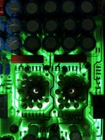
The circuit board has traces on both sides and some pass underneath the smt components so it's hard to tell if it is connected to the component or not. You can see in the flashlight photo in my first post. I stared at it for a long time last night wondering if I could draw it out without going crazy 🙂 Since nobody has in 21 years (at least publicly on the web) I'm a little doubtful.
You can use a DVM to check for continuity between two points on the board.
Just start at the tube socket pins 1,2,3 and 6,7,8 and go from there.
Just start at the tube socket pins 1,2,3 and 6,7,8 and go from there.
OK thanks, will take a stab at it. Or at least enough to get some ideas. I have a feeling it will be less overwhelming once I start.
Most things are, just be sure to unplug it. A flashlight on the other side of the board may help.
I took pictures extensively with the flashlight behind the board last time I had it apart. I hope to be able to work off those except when I need to test a connection.
This is probably impossible to answer, but let's just say I left it "good enough for rock n roll" with my output level hack in place where one channel is configged for 2.5V and the other 1.25V. Do you think I'm overdriving the tubes or anything like that? Anything that is likely to meltdown or ultimately damage tubes? Or is it more likely I'm losing signal before or after the tubes.
This is probably impossible to answer, but let's just say I left it "good enough for rock n roll" with my output level hack in place where one channel is configged for 2.5V and the other 1.25V. Do you think I'm overdriving the tubes or anything like that? Anything that is likely to meltdown or ultimately damage tubes? Or is it more likely I'm losing signal before or after the tubes.
A friend of mine have a Njoe Tjoeb, and (too) many years ago we put in 2 new SMD-caps. Unfortunately we're too old to remember why, but the name of the guy who originally built it is Herman van den Dungen, he is on Facebook, and I'm told that he is happy to help. I would give it a shot.
You will not damage anything by setting different output for each channel.
You will not damage anything by setting different output for each channel.
A friend of mine have a Njoe Tjoeb, and (too) many years ago we put in 2 new SMD-caps. Unfortunately we're too old to remember why, but the name of the guy who originally built it is Herman van den Dungen, he is on Facebook, and I'm told that he is happy to help. I would give it a shot.
You will not damage anything by setting different output for each channel.
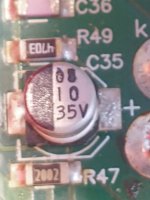
Interesting. I found one post out there on the internet where a guy said he replaced C35 and C37 which are the little can caps next to the WIMAs. He didn't say anything about why he did it but I got the feeling like at the time, back in 2006 or so, people knew of a common issue with the caps.
I was wondering if Herman would entertain questions about such an old device. Looks like he's moved on to fancier more expensive stuff these days so I didn't bother asking. Probably worth a try though.
That sounds like a good idea, give it a try and ask him if those capacitors could cause
a gain problem (up or down). Or maybe he'll have another idea, or even a schematic.
a gain problem (up or down). Or maybe he'll have another idea, or even a schematic.
Pinged him and no response yet. But I decided to do some more signal tracing and discovered that the signal entering the C35 and C37 is balanced and the signal "exiting" not balanced. So I took the chance to remove the surface mount caps and replace with some 10uF Nichicon caps I have around. Signal is now perfectly balanced at the amp, but both channels are lower than before. So as I suspected I think the right channel was too high before and even the left signal was too high (but less so). The only thing is I'm not sure 10uF is correct, can somebody tell me how to read the numbers on this cap? The old caps measured .11 and .14nF.
Attachments
- Home
- Amplifiers
- Tubes / Valves
- Ah! Njoe Tjoebe Channel Imbalance