Anybody got one?
Current source, TO-92, 3pin, V+in, Set, V-in
Iset = 227[uA/K] x (273 + 25)[K] / Rset = 67.7 / Rset [mA] ;@25°C
Current source, TO-92, 3pin, V+in, Set, V-in
Iset = 227[uA/K] x (273 + 25)[K] / Rset = 67.7 / Rset [mA] ;@25°C
Last edited:
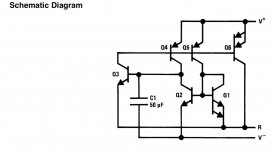
Can't you make one from the internal schematic as published in the datasheet?
See the last page of https://www.ti.com/lit/gpn/lm334 If I reverse engineered it properly, Q1 consists of about 12 devices in parallel and Q6 of 16 devices in parallel.
See the last page of https://www.ti.com/lit/gpn/lm334 If I reverse engineered it properly, Q1 consists of about 12 devices in parallel and Q6 of 16 devices in parallel.
Last edited:
You could use default Spice transistors; the scaling factors are critical, but the precise transistor parameters should not be.
With not work at all, do you mean you only got leakage currents? If so, you could put a very large resistor between the collector and emitter of Q3 to help it start up.
With not work at all, do you mean you only got leakage currents? If so, you could put a very large resistor between the collector and emitter of Q3 to help it start up.
Thank you!I have found the attached one.
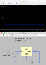
This is the one i found too and it is not working. You can easy find out by building just a simple Iset model (one LM334, one R and a power source). No matter what you choose for Rset, Iset does not change…
The setup —should— work as follows:
Iset = 227uV/K x (273 + 25) / Rset = 67.7 / Rset ;Iset [mA] at 25°C
LM334 can be used as linear Temperatur sensor too!
Attachments
Last edited:
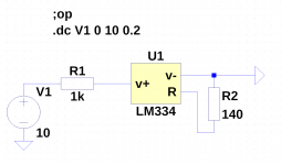
I've been using this model for a long time without any problems. You didn't post your symbol file but you might want to double-check the pin order. This LM334 subcircuit specifies a pin order of V+ V- R, which I believe would correspond to your pin labels In Out Adj. A lot of the LTspice 3-terminal regulator symbols (if you adapted your symbol from one of those) use the pin order Adj Out In.This is the one i found too and it is not working. You can easy find out by building just a simple Iset model (one LM334, one R and a power source). No matter what you choose for Rset, Iset does not change…
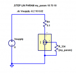
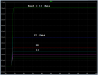
Also, you might want to run your test simulation using the .op directive instead of a transient analysis. There is no AC stimulus (that I can see) and I think you are trying to see what DC current is sunk from the power supply in this circuit. Using this subcircuit and my own symbol, I get 489 uA.
I don't know how accurate the model is at low currents like this, so conducting a test with an actual circuit would be a good idea.
Last edited:
Attached is a ZIP file containing Helmut's LM334 model file, along with his symbol file and a test file. These were downloaded from the LTspice Users Group at the Groups.io forums site.
I should note that the SPICE model file in the ZIP archive is an updated one; the one attached in post # 5 is labeled "old" in the LTspice Users Group file section. I recommend using this one instead of the "old" one.
I should note that the SPICE model file in the ZIP archive is an updated one; the one attached in post # 5 is labeled "old" in the LTspice Users Group file section. I recommend using this one instead of the "old" one.
Attachments
Last edited:

- Home
- Design & Build
- Parts
- LM334 Working Spice Model