Hi.
I bought a Heathkit SA-3 integrated amp about a year ago, and after doing a rebuild - new caps/resistors - couldn't get it to work.
So, I tore it down completely, made a new "enclosure" and built a new amp from the "bits"
Powered it up safely, and no blue smoke or magic sparkles.
Sounds very nice with a couple of caveats...
The Volume knob is insanely sensitive. Reaches full volume at about 8/9 o'clock, and if it gets dialled up further, there is no change in volume. It also starts to distort quite a bit before it reaches max volume - gets grainy and "scuzzy" (Max volume is not very loud). Granted, I realize this is a flea watt amp, but I'm running it into 90db speakers and feel it should be louder overall?
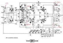
I removed both the treble (C10 & C11/R13 & R14) and bass control (C17 & C18/R29 & R30) as I didn't want them and wondering if this might have something to do with it?
Also, there is a small cap (C1 & C2) as well as a resistor (R1 and R2) on the RCA inputs. Wondering what they do? Are they a filter of some sort?
Thank you!
Per
I bought a Heathkit SA-3 integrated amp about a year ago, and after doing a rebuild - new caps/resistors - couldn't get it to work.
So, I tore it down completely, made a new "enclosure" and built a new amp from the "bits"
Powered it up safely, and no blue smoke or magic sparkles.
Sounds very nice with a couple of caveats...
The Volume knob is insanely sensitive. Reaches full volume at about 8/9 o'clock, and if it gets dialled up further, there is no change in volume. It also starts to distort quite a bit before it reaches max volume - gets grainy and "scuzzy" (Max volume is not very loud). Granted, I realize this is a flea watt amp, but I'm running it into 90db speakers and feel it should be louder overall?
I removed both the treble (C10 & C11/R13 & R14) and bass control (C17 & C18/R29 & R30) as I didn't want them and wondering if this might have something to do with it?
Also, there is a small cap (C1 & C2) as well as a resistor (R1 and R2) on the RCA inputs. Wondering what they do? Are they a filter of some sort?
Thank you!
Per
Attachments
The volume control should be a Linear type, not Log.
If you remove the "bass" control, you will remove the nfb loop. The distortion and gain will be uncontrolable.
C1/2 are HF filters in an attempt to stop interference arriving on the preamp input.
R1/2 stop the output from a tuner from storing a DC voltage and causing a click/pop sound when selecting it from the other selection.
The bass control pot + cap is also part of the negative feedback loop , so it was unwise to remove them completely . Those parts should be shunted/replaced with wires . Now without negative feedback the amplification is at maximum and probably overall performance is also not very good .
The input caps to ground are for phono , for optimum response from some old ceramic cartridges ... you can remove them
The input caps to ground are for phono , for optimum response from some old ceramic cartridges ... you can remove them
Last edited:
Thank you!The volume control should be a Linear type, not Log.
If you remove the "bass" control, you will remove the nfb loop. The distortion and gain will be uncontrolable.
C1/2 are HF filters in an attempt to stop interference arriving on the preamp input.
R1/2 stop the output from a tuner from storing a DC voltage and causing a click/pop sound when selecting it from the other selection.
While I have no idea how a negative feedback loop works, what you say makes sense 🙂
And I’m using the original volume pot from the Heathkit, but intend on replacing it with a new “proper” one. Figured I would get the thing working properly before I bought any more parts.
Thank you!The bass control pot + cap is also part of the negative feedback loop , so it was unwise to remove them completely . Those parts should be shunted/replaced with wires . Now without negative feedback the amplification is at maximum and probably overall performance is also not very good .
The input caps to ground are for phono , for optimum response from some old ceramic cartridges ... you can remove them
Happy to not put them back!
As far as returning the bass control/negative feedback into the circuit with wires/fixed value components, where do I start at selecting values and how should I implement the jumper that goes from the left to the right?
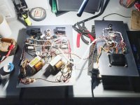
This is where the amp currently sits from a wiring standpoint…
Attachments
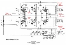
I would use a just a wire there , and of course the cap must be eliminated too . Like in the schematic from post #5
Thanks!I would use a just a wire there , and of course the cap must be eliminated too . Like in the schematic from post #5
That’s what I have hooked up currently, just the wire? And the distortion/grain/volume issue is present with the wire connected. There is a dotted “jumper” going from the left to the right. Any thoughts on what to do about that?
Per
The dotted line means that the pot is dual ...
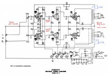
If the gain is too high you can replace the resistor R24 27K ( and the equivalent on the other channel ) with a lower one , lets say 10K . More negative feedback , less gain .
The root cause is that it has 2 stages of amplification before the power tube , usually 1 is enough for a single ended like this .
It was made for turntable phono input so it is very sensitive , maybe 100mV rms or even less for full power .
Thanks again!
I think I understand… I gather ceramic cartridges have a higher output than MM?
Would putting C1/C2 & R1/R2 help to reduce the line sensitivity?
If I were to put the bass control back in - and have it “fixed” as I’ve drawn, would that have any effect on the negative feedback?
Please forgive all the questions - trying to learn as much as possible as I go along 🙂
Per
(Oh, and thank you re: dotted line. I thought that’s what it might be, but wasn’t sure. New to reading schematics obviously…)
Yes ceramic cartridge has much more output than MM .Thanks again!
I think I understand… I gather ceramic cartridges have a higher output than MM?
Would putting C1/C2 & R1/R2 help to reduce the line sensitivity?
If I were to put the bass control back in - and have it “fixed” as I’ve drawn, would that have any effect on the negative feedback?
Please forgive all the questions - trying to learn as much as possible as I go along 🙂
Per
C1 C2 R1 R2 don't change the input sensitivity
Even if you put back bass control the sensitivity would be about the same ( in fact probably higher ) .
Maybe the treble circuit would have some effect in reducing the sensitivity but not dramatic
I see two option , increase the negative feedback as I said , or remove the input pentode stage and feed the signal directly in the triode .
Woo hoo!!!
I found the problem. I had the input/output of the volume pot wired wrong.
The center had the signal comIng in, the side had the signal going out.
Now it is as it should be.
Feeling a bit dumb…
Sorry to have wasted your time, but thank you for your thoughts, as I doubt I would have found this without digging through the other issues you pointed out.
So happy!
This sounds so good now.
Thank you!
Per
- Home
- Amplifiers
- Tubes / Valves
- Fresh EL84 integrated SET build - gain issues...